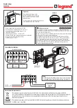
OS, operating mode selector
switch
455
02/16 MN05013001Z EN
Example
Use of the operating mode switch with 3 switch positions.
Actuating a key switch allows the operating mode change.
The actual change is implemented with an acceptance
button.
The connections are implemented as follows:
• Operating mode switch S1 at device terminals IS1 to IS3.
• Key switch S2 at device terminal IS6.
• Acceptance button S3 at device terminal IS8.
This looks as follows in the electrical circuit diagram:
Figure 231:
"Operating mode switch" example: electrical
circuit diagram
0 V
+24 V
2
1
-F1
S 1A
T1
T2
T3
T4
4x Test Signal
Output 4x Relay / 6A
DEL
-K1
OK
ALT
ES4P-221-DRXD1
DC 24 V
NET
Input 14 x DC
ESC
IS1
IS2
IS3
IS4
IS5
IS6
IS7
IS8
IS9 IS10 IS11 IS12 IS13 IS14
1
QS1
2 1
QS2
2 1
QS3
2 1
QS4
2
+24V 0V
0V
P1
P2
P3
P4
I
0
-S2
31
41
1
2
3
4
5
6
-S1
1 2 3
31
41
-S3
ea ySafety
Summary of Contents for easySafety
Page 1: ...Manual Control relay suitable for safety circuits Safety ES4P 02 16 MN05013001Z EN ...
Page 4: ...2 ...
Page 42: ...38 02 16 MN05013001Z EN ...
Page 80: ...Installation 76 02 16 MN05013001Z EN ...
Page 112: ...108 02 16 MN05013001Z EN ...
Page 606: ...602 02 16 MN05013001Z EN ...