


Safety function blocks
370
02/16 MN05013001Z EN
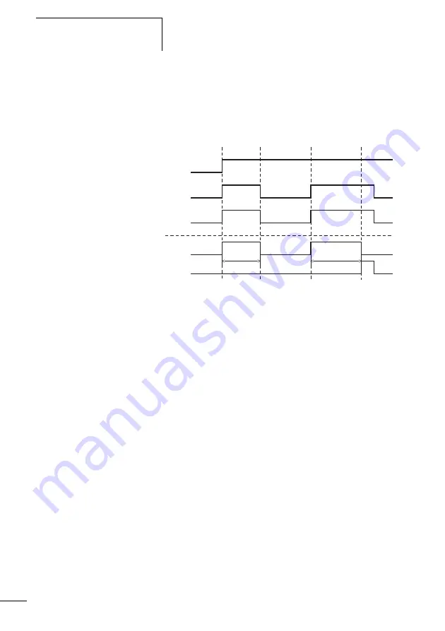
The signal diagram of the function block for this application
shows the dependence of the enable contact EN01QS on the
status of coils EN01SA, EN01I1 and EN01I2 as well as the
timeout of the enable time:
Figure 184:
Enable switch example:
Enable switch positions:
a
The key switch is in the position for setting operation and the
motor speed is slow. The enable switch can therefore be acti-
vated.
b
Actuation of the enable switch (switch position 1). The enable
time is less than the time set at ED. The enable at EN01QS is
initiated.
c
Release of the enable switch, the enable at EN01QS is removed.
d
Actuation of the enable switch (switch position 1). The enable
time is greater than the time set at ED. The enable at EN01QS
is removed after the enable time has elapsed. The function
block outputs an error signal via EN01ER.
e
Acknowledgement of the error signal by releasing the enable
switch.
EN01I1
EN01I2
EN01QS
EN01ER
EN01SA
t < ED
t > ED
a
b
c
e
d
Summary of Contents for easySafety
Page 1: ...Manual Control relay suitable for safety circuits Safety ES4P 02 16 MN05013001Z EN ...
Page 4: ...2 ...
Page 42: ...38 02 16 MN05013001Z EN ...
Page 80: ...Installation 76 02 16 MN05013001Z EN ...
Page 112: ...108 02 16 MN05013001Z EN ...
Page 606: ...602 02 16 MN05013001Z EN ...


