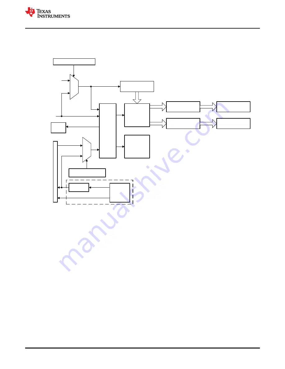
5.3 Operational Details
shows the various components that implement the high-resolution, pulse-width capture functionality of
the module.
HCCAPCNTRISE0
HCCAPCNTFALL0
HCCAPCNTRISE1
HCCAPCNTFALL1
16
16
16
16
HRCAP
Counter
Capture Logic
HRCAP
Calibration
Logic
HRCAP
Edge
Detect
Logic
HCCOUNTER
0
1
0
1
PIE
SYSCLKOUT
PLL2CLK
HCCAL[HRPWMSEL]
HRPWM
G
P
I
O
M
U
X
EPWMxA
EPWMx
EPWMxB
HCCAPCLK
(A)
HCCTL[HCCAPCLKSEL]
16
HRCAPx
HRCAP_cal
HRCAPxINTn
A.
If PLLCLK is selected as the source for HCCAPCLK, HCCAPCLK is asynchronous to SYSCLK.
Figure 5-2. HRCAP Block Diagram
5.3.1 HRCAP Clocking
Although the HRCAP module is clocked by the system clock, the 16-bit counter (HCCOUNTER) and edge
detection logic used for capturing high-resolution pulses is clocked by HCCAPCLK. HCCAPCLK must fall within
the frequency range specified in the
Electricals
section of the device-specific data manual. HCCAPCLK can
either be clocked by the system clock (SYSCLK), or the output of the PLL2 (PLL2CLK) before the divider
is applied. If HCCAPCLK is fed from the PLL2CLK (HCCTL[HCCAPCLKSEL] = 1), then HCCAPCLK will be
asynchronous to SYSCLK2. On this device, HCCAPCLK is clocked by SYSCLKOUT or PLL2.
shows how the HCCAPCLK that clocks the HCCOUNTER and edge detection logic is generated.
High-Resolution Capture (HRCAP) Module
SPRUH18I – JANUARY 2011 – REVISED JUNE 2022
TMS320x2806x Microcontrollers
407
Copyright © 2022 Texas Instruments Incorporated
Содержание TMS320 2806 Series
Страница 2: ......


