


12-
6
750/760 Feeder Management Relay
GE Power Management
12.2 DIRECTIONAL OVERCURRENT CHARACTERISTICS
12 S5 PROTECTION
12
12.2 DIRECTIONAL OVERCURRENT CHARACTERISTICS
12.2.1 DESCRIPTION
Directional overcurrent relaying is necessary for the protection of multiple source feeders, when it is essential
to discriminate between faults in different directions. It would be impossible to obtain correct relay selectivity
through the use of a non-directional overcurrent relay in such cases. Fault directional control (ANSI device 67)
is incorporated into the relay for all phase, neutral, sensitive ground, and negative sequence overcurrent ele-
ments. If directional control is selected, it will determine whether current flow in each phase is in the forward or
reverse direction, as determined by the connection of the phase source CTs, selected MTA angle, voltage and
current phasors. Each overcurrent element can be individually programmed to operate for flow only in specific
directions. For increased security, all overcurrent elements under directional control add one power frequency
cycle of intentional delay to prevent operational errors on current ‘swings’.
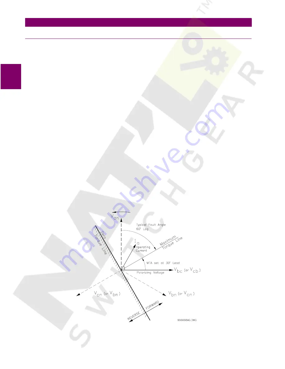
Some terms commonly used in directional relaying are defined as:
•
Operating Current
: the quantity whose directionality is to be tested.
•
Polarizing Voltage:
a voltage whose phase will remain reasonably constant between a non-faulted and a
faulted system, used as a phase reference for the operating current.
•
Relay Connection:
for phase directional relaying, the characteristic angle between the operating current
and the polarizing voltage in the non-faulted system.
•
Zero Torque Line:
the boundary line between operating and blocking regions in the complex plane; in an
electromechanical directional relay, an operating current near this line generates minimum torque.
•
Maximum Torque Line:
the line perpendicular, through the origin, to the Zero Torque Line in the complex
plane; in an electromechanical directional relay, an operating current near this line will generate a maxi-
mum amount of torque.
•
Maximum Torque Angle (MTA):
the angle by which the Maximum Torque Line is rotated from the Polariz-
ing Voltage.
The following diagram specifically shows the phasors involved for phase A directional polarization, but the gen-
eral principles can be applied to all directional elements.
Figure 12–1: PHASE A DIRECTIONAL OVERCURRENT POLARIZING
Содержание 750
Страница 2: ......
Страница 4: ......
Страница 124: ...8 14 750 760 Feeder Management Relay GE Power Management 8 12 INSTALLATION 8 S1 RELAY SETUP 8 ...
Страница 144: ...10 14 750 760 Feeder Management Relay GE Power Management 10 10 MISCELLANEOUS FUNCTIONS 10 S3 LOGIC INPUTS 10 ...
Страница 152: ...11 8 750 760 Feeder Management Relay GE Power Management 11 3 OUTPUT RELAYS 3 7 AUXILIARY 11 S4 OUTPUT RELAYS 11 ...
Страница 216: ...12 64 750 760 Feeder Management Relay GE Power Management 12 9 BREAKER FAILURE 12 S5 PROTECTION 12 ...
Страница 484: ...17 78 750 760 Feeder Management Relay GE Power Management 17 10 PLACING THE RELAY IN SERVICE 17 COMMISSIONING 17 ...
Страница 488: ...A 4 750 760 Feeder Management Relay GE Power Management A 1 FIGURES AND TABLES APPENDIXA A ...
Страница 490: ...B 2 750 760 Feeder Management Relay GE Power Management B 1 EU DECLARATION OF CONFORMITY APPENDIXB B ...
Страница 492: ...C 2 750 760 Feeder Management Relay GE Power Management C 1 WARRANTY INFORMATION APPENDIXC C ...
Страница 502: ...x 750 760 Feeder Management Relay GE Power Management INDEX ...
Страница 503: ...GE Power Management 750 760 Feeder Management Relay NOTES ...


