17-
68
750/760 Feeder Management Relay
GE Power Management
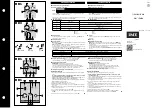
17.9 CONTROL SCHEMES
17 COMMISSIONING
17
h) MANUAL RESTORATION OF INCOMER 1
1.
Turn test Source 1 on and adjust Source 1 to be out-of-synchronism with Source 2.
2.
At the Bus Tie relay assert Logic Input No. 06 (Selected To Trip.)
3.
At the Incomer 1 relay assert Logic Input No. 02 (Remote Close.) The Incomer 1 breaker should not close
as it cannot pass synchrocheck. Adjust Source 1 until in-synchronism with Source 2. At this time the
Incomer 1 breaker should close and the Bus Tie breaker should trip. Turn off both voltages.
4.
At the Bus Tie relay de-assert Logic Input No. 06 (Selected To Trip.) Check the Event Recorders in the
Incomer 1 and Bus Tie relays for the correct messages and sequences, then clear the recorders.
i) TRANSFER INITIATED BY UNDERVOLTAGE ON SOURCE 2
1.
Energize both test sources at nominal voltage, and wait until the Transfer Not Ready message is removed
from the display of both Incomer relays.
2.
Turn test Source 2 off. The Undervoltage 3 feature of Incomer 2 relay should operate immediately and
operate output relay 4; at the Incomer 1 relay output relay 3 will operate and the Transfer Not Ready mes-
sage will be displayed. When the Undervoltage 4 feature times-out the Incomer 2 relay should trip Incomer
breaker 2 and operate output relay 6 to send a Close From Incomer 2 signal to the Bus Tie relay. Output
relay 6 should reset when breaker 2 trips, removing the signal to the Bus Tie relay. Upon receiving the sig-
nal from the Incomer 2 relay the Bus Tie relay should close the Bus Tie Breaker.
3.
Check the Event Recorders in the Incomer 2 and Bus Tie relays for the correct messages and sequences,
then clear the recorders.
j) MANUAL RESTORATION OF INCOMER 2
1.
Turn test Source 2 on and adjust Source 2 to be out-of-synchronism with Source 1.
2.
At the Bus Tie relay assert Logic Input No. 06 (Selected To Trip.
3.
At the Incomer 2 relay assert Logic Input No. 02 (Remote Close.) The Incomer 2 breaker 2 should not
close as it cannot pass synchrocheck. Adjust Source 2 until in-synchronism with Source 1. At this time the
Incomer 2 breaker should close and the Bus Tie breaker should trip. Turn off both voltages.
4.
At the Bus Tie relay de-assert Logic Input No. 06 (Selected To Trip.)
5.
Check the Event Recorders in the Incomer 2 and Bus Tie relays for the correct messages and sequences,
then clear the recorders.
k) SIMULTANEOUS LOSS OF BOTH SOURCES
1.
Energize the line voltage input of both incomer relays from a single source at nominal voltage, and wait
until the Transfer Not Ready message is removed from the display of both relays.
2.
Turn the test source off. The Undervoltage 3 element of both incomer relays should operate immediately
and operate output relay 4; at both incomers the Transfer Not Ready message will be displayed.
If setpoint
BLOCK TRIP ON DOUBLE LOSS
is set to Disabled:
3.
When the Undervoltage 4 element times-out the incomer relays should trip the incomer break-
ers. The bus tie breaker should not close.
4.
Check the Event Recorders in both incomer relays for the correct messages and sequences,
then clear the recorders.
If setpoint
BLOCK TRIP ON DOUBLE LOSS
is set to Enabled:
1.
2.
3.
When the Undervoltage 4 element times-out the incomer relays should not trip the incomer
breakers. The bus tie breaker should not close.
4.
Check the Event Recorders in both incomer relays for the correct messages and sequences,
then clear the recorders.
Содержание 750
Страница 2: ......
Страница 4: ......
Страница 124: ...8 14 750 760 Feeder Management Relay GE Power Management 8 12 INSTALLATION 8 S1 RELAY SETUP 8 ...
Страница 144: ...10 14 750 760 Feeder Management Relay GE Power Management 10 10 MISCELLANEOUS FUNCTIONS 10 S3 LOGIC INPUTS 10 ...
Страница 152: ...11 8 750 760 Feeder Management Relay GE Power Management 11 3 OUTPUT RELAYS 3 7 AUXILIARY 11 S4 OUTPUT RELAYS 11 ...
Страница 216: ...12 64 750 760 Feeder Management Relay GE Power Management 12 9 BREAKER FAILURE 12 S5 PROTECTION 12 ...
Страница 484: ...17 78 750 760 Feeder Management Relay GE Power Management 17 10 PLACING THE RELAY IN SERVICE 17 COMMISSIONING 17 ...
Страница 488: ...A 4 750 760 Feeder Management Relay GE Power Management A 1 FIGURES AND TABLES APPENDIXA A ...
Страница 490: ...B 2 750 760 Feeder Management Relay GE Power Management B 1 EU DECLARATION OF CONFORMITY APPENDIXB B ...
Страница 492: ...C 2 750 760 Feeder Management Relay GE Power Management C 1 WARRANTY INFORMATION APPENDIXC C ...
Страница 502: ...x 750 760 Feeder Management Relay GE Power Management INDEX ...
Страница 503: ...GE Power Management 750 760 Feeder Management Relay NOTES ...