


4-3
Section
Axis Parameter Area
72
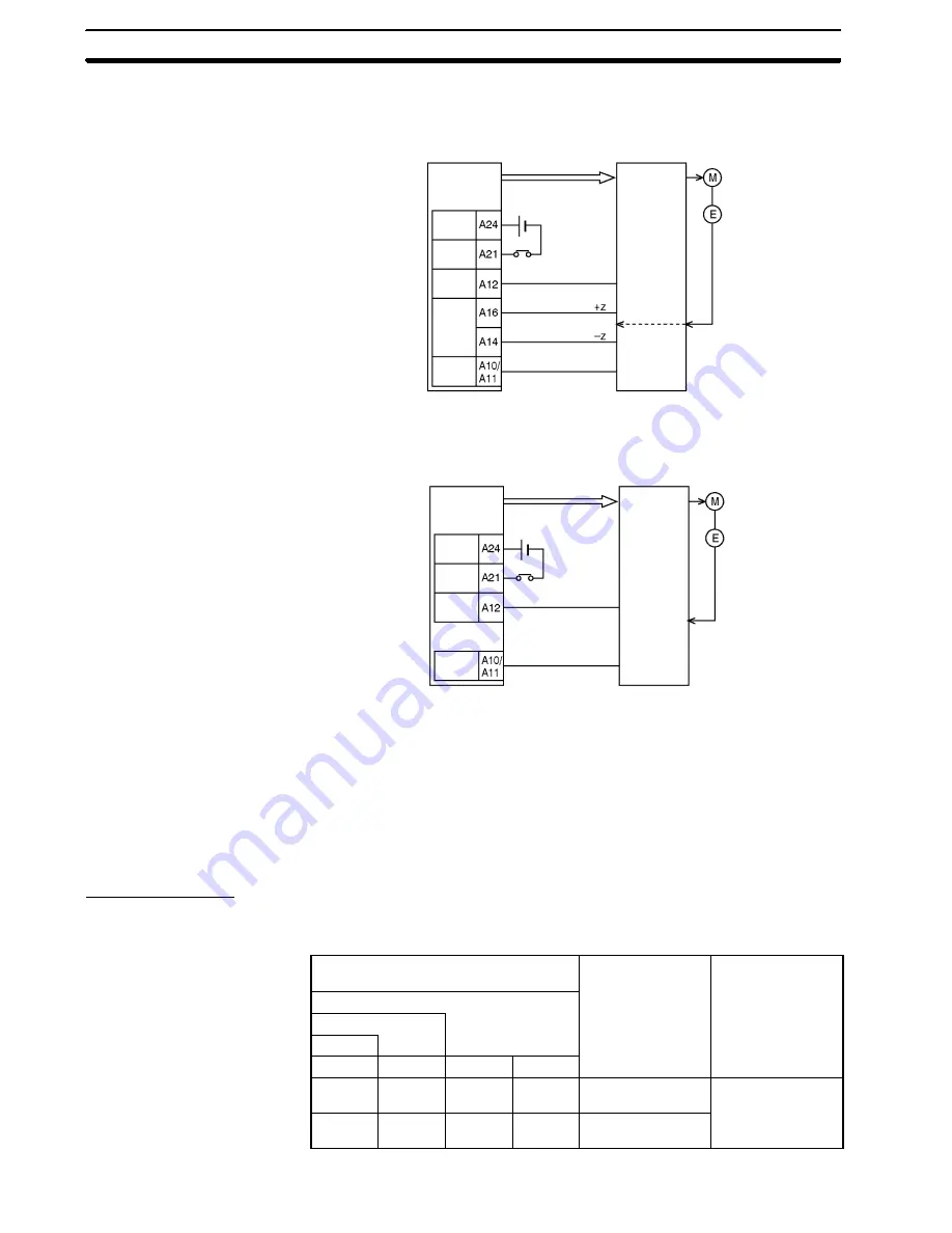
Set mode 2 when using a servo motor drive and connecting a line driver input
and a error counter reset output just as in mode 1, but when also using a posi-
tioning completed signal.
IC
X axis
PCU
Pulses
24 VDC
OPI
PCSI
OS
DCRO
DCRI
Serv
motor
drive
Z-phase
output
PCSO
Set mode 3 when using a servo motor drive and also using the origin adjustment
command.
IC
X axis
PCU
Pulse
24 VDC
OPI
PCSI
OACO
OACI
Serv
motor
drive
PCSO
For details on operation mode settings, refer to
6-4 Origin Search Operation
.
Note
In the wiring examples for modes 1 to 3, the servo motor drive used is an
OMRON R88D Servo Motor Drive. Set the servo motor drive so that the servo
motor drive’s positioning completed signal is OFF during motor operation and
ON while the motor is stopped. If this setting is not made, positioning may
become impossible without the positioning completed signal in the operating
memory area turning ON.
Maximum Speed
The word address and enable timing for the maximum speed setting is shown
below.
Word
(PCU internal address)
Name
Enable timing
NC1
j
3
NC2
j
3
NC4
j
3
X axis
Y axis
Z axis
U axis
m+6
(0006)
m+34
(0022)
m+62
(003E)
m+90
(005A)
Maximum speed
(rightmost word)
With operating
command
m+7
(0007)
m+35
(0023)
m+63
(003F)
m+91
(005B)
Maximum speed
(leftmost word)
co
a d
Mode 2
Mode 3
Word Address and
Enable Timing
Summary of Contents for CS1W-NC113 - REV 02-2008
Page 1: ...CS1W NC113 213 413 133 233 433 Position Control Units ...
Page 2: ...iv ...
Page 4: ...vi ...


