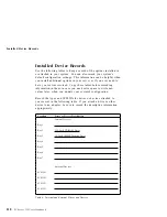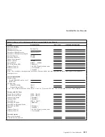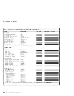
Installed Device Records
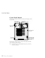
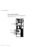
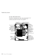
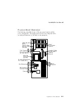
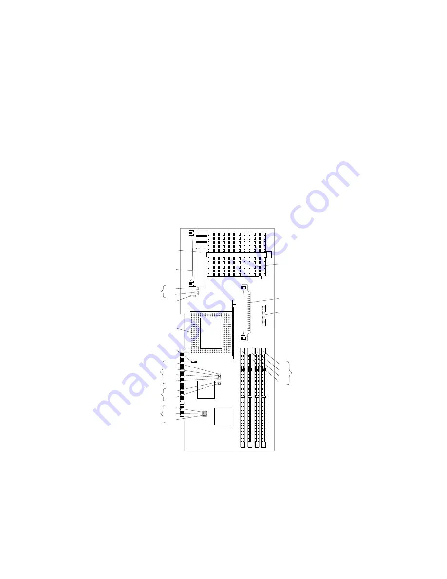
Processor Board Illustration
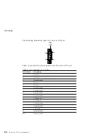
The following simplified layout of the processor board identifies
server components. You might need to refer to the diagram when
recording information in the tables in this appendix.
Primary
Microprocessor
Connector
Secondary Voltage
Regulator Module
Connector
Reserved
Memory
Connectors
Secondary
Microprocessor
Connector
Primary Microprocessor
Fan Connector (J22)
Secondary Microprocessor
Fan Connector (J21)
Primary Voltage
Regulator Module
Connector
Voltage Regulator
Module
Clock Frequency
J1
J20
PMC Frequency
Selection Jumper
Clock Ratio Jumper
J30
J29
J28
J27
J2
J3
J4
J5
J9
J10
J12
J17
J18
Reserved
Appendix B. Server Records
223
Summary of Contents for PC Server 325
Page 1: ...PC Server 325 User s Handbook IBM...
Page 6: ...vi PC Server 325 User s Handbook...
Page 10: ...Laser Compliance Statement x PC Server 325 User s Handbook...
Page 136: ...Updating the Server Configuration 122 PC Server 325 User s Handbook...
Page 212: ...Resolving Configuration Conflicts 198 PC Server 325 User s Handbook...
Page 238: ...Installed Device Records 224 PC Server 325 User s Handbook...
Page 287: ......
Page 288: ...IBM Part Number 76H8831 Printed in U S A September 1996 76H8831...

