


Working with Memory-Module Kits
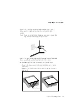
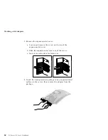
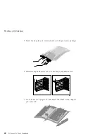
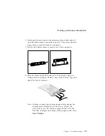
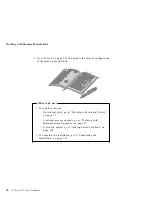
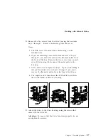
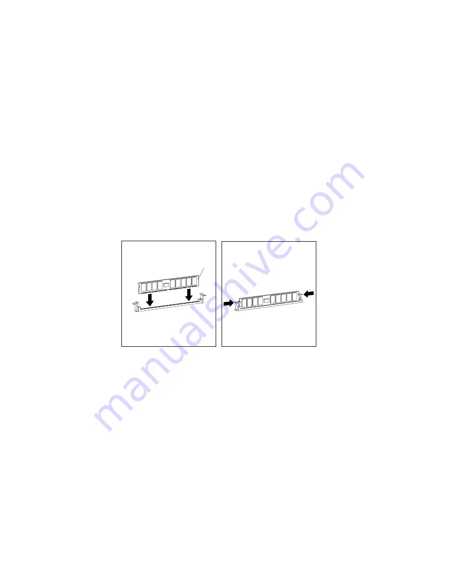
4. Position the DIMM so that the two key slots (openings in the
connector pins) on the bottom edge align with the
corresponding sections in the connector.
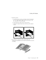
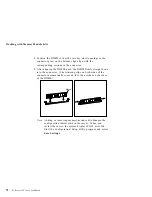
5. After aligning the DIMM, push the DIMM firmly straight down
into the connector. (The retaining clips on both sides of the
connector automatically come up into the notches on the sides
of the DIMM.)
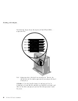
Notch
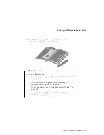
Note: Adding or removing memory-module kits changes the
configuration information in the server. When you
restart the server, the system displays POST error 164.
Start the Configuration/Setup utility program and select
Save Settings.
72
PC Server 325 User's Handbook
Summary of Contents for PC Server 325
Page 1: ...PC Server 325 User s Handbook IBM...
Page 6: ...vi PC Server 325 User s Handbook...
Page 10: ...Laser Compliance Statement x PC Server 325 User s Handbook...
Page 136: ...Updating the Server Configuration 122 PC Server 325 User s Handbook...
Page 212: ...Resolving Configuration Conflicts 198 PC Server 325 User s Handbook...
Page 238: ...Installed Device Records 224 PC Server 325 User s Handbook...
Page 287: ......
Page 288: ...IBM Part Number 76H8831 Printed in U S A September 1996 76H8831...