Working with Microprocessor Upgrades
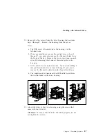
3. Touch the static-protective package containing the new
microprocessor to any unpainted metal surface on the server;
then remove the microprocessor from the package. Place it
pin-side down on the static-protective foam that it came shipped
on.
4. Both microprocessors on a processor board must have the same
internal and external clock speed and cache size to ensure
proper server operation.
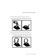
5. Open the thermal grease packet, and empty the contents evenly
across the heat spreader (the raised, gold area on the top of the
microprocessor).
Note: If thermal grease touches your skin, wash your hands
with soap and water.
6. Position the fan sink above the microprocessor, aligning the heat
spreaders; then, place the fan sink on the microprocessor.
7. Slide the fan sink back and forth across the microprocessor
several times to ensure that the thermal grease fully covers both
heat-spreaders.
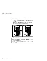
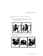
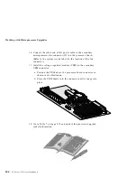
8. Align the edges of the microprocessor and fan sink, and press
firmly.
Note: When you move the microprocessor/fan sink assembly to
the socket on the processor board, be sure to hold the
edges of both the fansink and the microprocessor. This
maintains the alignment and helps to reduce the risk of
dropping the assembly.
Chapter 3. Installing Options
101
Summary of Contents for PC Server 325
Page 1: ...PC Server 325 User s Handbook IBM...
Page 6: ...vi PC Server 325 User s Handbook...
Page 10: ...Laser Compliance Statement x PC Server 325 User s Handbook...
Page 136: ...Updating the Server Configuration 122 PC Server 325 User s Handbook...
Page 212: ...Resolving Configuration Conflicts 198 PC Server 325 User s Handbook...
Page 238: ...Installed Device Records 224 PC Server 325 User s Handbook...
Page 287: ......
Page 288: ...IBM Part Number 76H8831 Printed in U S A September 1996 76H8831...

