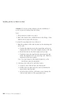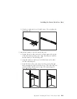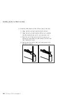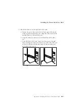
Preparing a Tower Model for Rack Installation
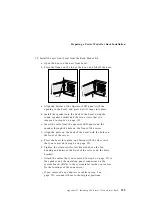
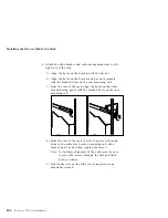
10. Install the new front bezel from the Rack Mount Kit.
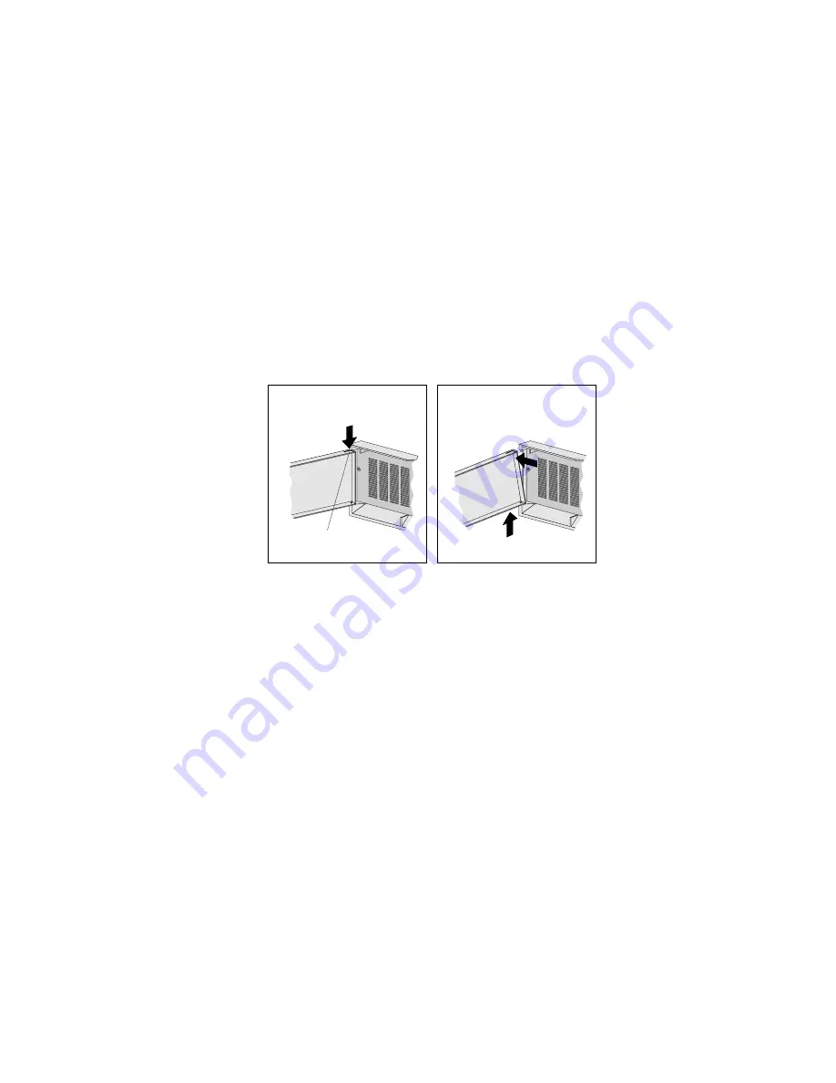
a. Open the door on the new front bezel.
b. Press the flange on the top of the door, and lift off the door.
Flange
c. Align the bottom of the Operator LED panel with the
opening in the bezel, and press until it snaps into place.
d. Install the speaker into the back of the bezel, using the
round speaker bracket and the two screws that you
removed in step 6c on page 233.
e. Insert the cable from the operator LED panel and the
speaker through the hole on the front of the server.
f. Align the posts on the back of the bezel with the holes on
the front of the server.
g. Press the bezel into place, and fasten with the six screws
that you removed in step 6a on page 233.
h. Tighten the strain relief screw (located above the fan
housing and between the front of the server and the drive
bracket).
i. Attach the cables that you removed in step 2 on page 231 to
the speaker and the operating panel connectors on the
system board. (Refer to the system label inside your server
for the locations of the connectors.)
j. If you removed any adapters or cables in step 3 on
page 231, reconnect them to the original positions.
Appendix D. Installing a PC Server 325 in a Server Rack
235
Summary of Contents for PC Server 325
Page 1: ...PC Server 325 User s Handbook IBM...
Page 6: ...vi PC Server 325 User s Handbook...
Page 10: ...Laser Compliance Statement x PC Server 325 User s Handbook...
Page 136: ...Updating the Server Configuration 122 PC Server 325 User s Handbook...
Page 212: ...Resolving Configuration Conflicts 198 PC Server 325 User s Handbook...
Page 238: ...Installed Device Records 224 PC Server 325 User s Handbook...
Page 287: ......
Page 288: ...IBM Part Number 76H8831 Printed in U S A September 1996 76H8831...


