AUI Cable
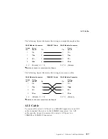
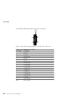
The following figure illustrates the wiring in straight-through cables.
Twisted
Pair
1
2
3
6
4, 5, 7, 8
RJ-45 Modular Connector
Pin
1
1
2
2
3, 4
10BASE-T Cable
1
2
3
6
4, 5, 7, 8
Pin
TD+
TD
RD+
RD
RJ-45 Modular Connector
(Not used)
TD+
TD
RD+
RD
(Not used)
Signal
Name
Signal
Name
Relative to the device connected to the Adapter
The following figure illustrates the wiring in crossover cables.
Twisted
Pair
1
2
3
6
4, 5, 7, 8
RJ-45 Modular Connector
Pin
1
1
2
2
3, 4
10BASE-T Cable
1
2
3
6
4, 5, 7, 8
Pin
TD+
TD
RD+
RD
RJ-45 Modular Connector
(Not used)
TD+
TD
RD+
RD
(Not used)
Signal
Name
Signal
Name
Relative to the device connected to the Adapter
AUI Cable
To connect the server's AUI port to a 10BASE5 segment, use an AUI
cable to connect the server to the 10BASE5 transceiver. An AUI
cable can also be used to connect the server's AUI port to a
10BASE2 or 10BASE-F transceiver.
Appendix C. Ethernet Cable Specifications
227
Summary of Contents for PC Server 325
Page 1: ...PC Server 325 User s Handbook IBM...
Page 6: ...vi PC Server 325 User s Handbook...
Page 10: ...Laser Compliance Statement x PC Server 325 User s Handbook...
Page 136: ...Updating the Server Configuration 122 PC Server 325 User s Handbook...
Page 212: ...Resolving Configuration Conflicts 198 PC Server 325 User s Handbook...
Page 238: ...Installed Device Records 224 PC Server 325 User s Handbook...
Page 287: ......
Page 288: ...IBM Part Number 76H8831 Printed in U S A September 1996 76H8831...

