Appendix A. Jumpers
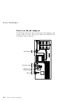
Jumpers located on the system board and the processor board help
you to customize the way your server operates.
Changing Jumper Positions
Your system board and processor board contain two-pin and
three-pin jumper blocks.
In some cases, groups of two-pin jumpers combine to define a
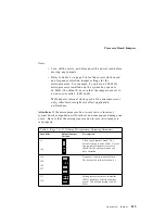
function. For example, the settings of jumpers J1 and J20 together
define the clock speed of the microprocessor.
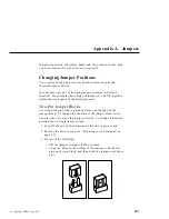
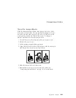
Two-Pin Jumper Blocks
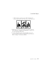
Covering both pins with a jumper defines one function of the
jumper block. To change the function of the jumper block, cover
one pin only or remove the jumper entirely. To change a jumper's
position for a two-pin jumper block:
1. Turn off the server; then disconnect the server power cord.
2. Remove the server cover (see “Preparing to Add Options” on
page 55).
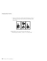
3. Do one of the following:
Lift the jumper straight off the pin block.
Align the holes in the bottom of the jumper with the two
pins on the pin block, and then slide the jumper onto these
pins.
Copyright IBM Corp. 1996
207
Summary of Contents for PC Server 325
Page 1: ...PC Server 325 User s Handbook IBM...
Page 6: ...vi PC Server 325 User s Handbook...
Page 10: ...Laser Compliance Statement x PC Server 325 User s Handbook...
Page 136: ...Updating the Server Configuration 122 PC Server 325 User s Handbook...
Page 212: ...Resolving Configuration Conflicts 198 PC Server 325 User s Handbook...
Page 238: ...Installed Device Records 224 PC Server 325 User s Handbook...
Page 287: ......
Page 288: ...IBM Part Number 76H8831 Printed in U S A September 1996 76H8831...

