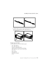
Preparing a Tower Model for Rack Installation
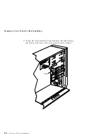
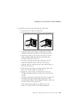
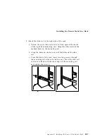
7. Position the server on its side on a desk or table with the floor
stand extending past the edge of the table.
8. Remove the floor stand.
a. Tilt the server on its side.
b. Remove the four screws on the bottom of the server.
c. Gently pull the floor stand from the bottom of the server.
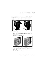
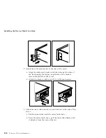
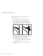
9. The Rack Mount Kit includes a replacement bezel and switch
cap for the operator LED panel; you can install them so that the
front cover of the drawer is all one color. If you do not want to
replace the bezel and switch cap, go to step 10 on page 235.
Otherwise, continue with the following steps.
a. Place the Operator LED assembly and the Operator LED
bezel from the Rack Mount Kit face down on a flat work
area.
b. Remove the three screws on the back of the Operator LED
panel assembly.
c. Carefully remove the front bezel and switch cap. Be sure
that you do not lose the spring, located inside the switch
cap.
d. Move the spring from the switch cap, and place it in the
switch cap from the Rack Mount Kit.
e. Attach the Operator LED panel to the new bezel, using the
three screws that you removed in step 9b.
234
PC Server 325 User's Handbook
Summary of Contents for PC Server 325
Page 1: ...PC Server 325 User s Handbook IBM...
Page 6: ...vi PC Server 325 User s Handbook...
Page 10: ...Laser Compliance Statement x PC Server 325 User s Handbook...
Page 136: ...Updating the Server Configuration 122 PC Server 325 User s Handbook...
Page 212: ...Resolving Configuration Conflicts 198 PC Server 325 User s Handbook...
Page 238: ...Installed Device Records 224 PC Server 325 User s Handbook...
Page 287: ......
Page 288: ...IBM Part Number 76H8831 Printed in U S A September 1996 76H8831...

