background image


in-use lights (continued)

diskette drive 5, 177

indicators, status 4
industry standard architecture (ISA)

See ISA (industry standard

architecture)

infrared port

See also the User's Reference
assignment  25
connector  8
location  9
port problems 182
problems  25

input/output connectors

See connector

installation

completing  111
cover  111
hardware  52
preparation  52, 55
sequence, for adapters 35

installing

adapters  63
cover  111
diskette drives 86, 88
drive housing 89, 94
external options 117
external SCSI connector 106
internal drives 81

diskette drives 86

memory-module kits 71
Option Diskettes 128
SCSI drives 79
security  110
tape drives 86
test programs 191
U-bolt  108

interfaces

See the User's Reference

intermittent problems 179
internal

device records 218, 219, 221
drives

cables  79
installing  81
purpose  77
removing  91

options, installed 219
preinstalled  10
SCSI devices, terminating 118

international warranty service 203
interrupt request (IRQ)

assigning PCI 33, 42
recording PCI 220
recording serial 219
sharing interrupts 40
viewing settings 24

IntruderAlert  134
ISA (industry standard architecture)

See also the User's Reference
adapter
adapter configuration 40
connector location 62
features and options 40

ISA adapters 40, 63

J

jumper

changing 63, 207, 212
locations  210
microprocessor frequency

selection  215

microprocessor-upgrade  100
power-on password (J12) 212
processor board

description  215
locations  214
microprocessor frequency

selection  215


Index

  261

Summary of Contents for PC Server 325

Page 1: ...PC Server 325 User s Handbook IBM...

Page 2: ...chnical inaccuracies or typographical errors Changes are periodically made to the information herein these changes will be incorporated in new editions of the publication IBM may make improvements and...

Page 3: ...ing Your Server 17 Configuration Overview 19 The Configuration Setup Utility 21 Using the Configuration Setup Utility Main Menu 22 Configuring Options 35 Using the EISA Configuration Diskette 36 Confi...

Page 4: ...m for Damage 189 Installing Additional Test Programs 191 Using the Utility Programs 194 Resolving Configuration Conflicts 196 Chapter 5 Getting Help Service and Information 199 Before You Call for Ser...

Page 5: ...5 in a Server Rack 229 Before You Begin 229 Preparing a Tower Model for Rack Installation 231 Installing the Drawer Model in a Rack 236 Removing the Drawer Model from a Rack 248 Appendix E Notices 251...

Page 6: ...vi PC Server 325 User s Handbook...

Page 7: ...s to devices In the U K by law the power cord must be disconnected after the telephone line cable 2 In the U K by law the telephone cable must be connected after the power cord 1 2 1 Electrical curren...

Page 8: ...que provenant des c bles d alimentation t lephoniques et de transmission peut pr senter un danger Pour viter tout risque de choc lectrique connectez et d connectez ces c bles comme indiqu ci dessous l...

Page 9: ...tional Electrotechnical Commission IEC 825 and CENELEC EN 60 825 for Class 1 laser products When a CD ROM drive is installed note the following CAUTION Use of controls or adjustments or performance of...

Page 10: ...Laser Compliance Statement x PC Server 325 User s Handbook...

Page 11: ...ions for using various utility programs Chapter 3 Installing Options contains instructions for installing and removing options such as memory adapters and internal drives Instructions for connecting e...

Page 12: ...lling a PC Server 325 in a Server Rack describes how to install the server in a 19 inch server rack Appendix E Notices contains product notices and trademarks An index follows the appendixes Notices U...

Page 13: ...ontains a parts catalog error codes and advanced diagnostic procedures This manual is intended for trained service technicians Diagnostic diskettes are not included The following pertain to the server...

Page 14: ...lists who can help you set up install and configure your server The PC Server 325 comes with a limited three year on site warranty In addition IBM s PC Server Startup Support provides coverage to PC S...

Page 15: ...bility is achieved by incorporating various quality standards and design points such as stringent IBM systems assurance testing Refer to the User s Reference for more detailed information on the serve...

Page 16: ...g 11 Arranging Your Workspace 13 Comfort 13 Glare and Lighting 14 Air Circulation 14 Electrical Outlets and Cable Lengths 15 Getting Help on the World Wide Web 15 IBM PC Server Startup Support 16 2 PC...

Page 17: ...PCI EISA slots One dedicated EISA slot Expansion Bays Two 5 25 inch drive bays Five 3 5 inch drive bays The number of bays available for expansion varies by model Upgradeable POST and BIOS POST BIOS...

Page 18: ...PC Server 325 Controls Tower model CD ROM Drive In Use Light Diskette Drive In Use Light Power Switch CD ROM Eject Button Diskette Eject Button Power On Light Drawer model CD ROM Drive In Use Light Di...

Page 19: ...the Standby mode if any of the drive In Use lights are on This might damage the information stored on a hard disk or diskette You can configure the server to start at a specified date and time or whe...

Page 20: ...Ethernet Receive Indicator Ethernet Transmit Indicator Security Indicator Ethernet Link Status Indicator 1 2 T Drawer model Unattended Power On Indicator Power On Indicator SCSI Hard Disk Drive Indic...

Page 21: ...activity on the network Security Indicator When tamper detection software is installed and enabled this amber LED shows that a security hardware error occurred Ethernet Link Status Indicator This gre...

Page 22: ...er Connector SCSI Knockout Parallel Connector Serial Connectors Expansion Slots Ethernet Connectors Keyboard Connector Mouse Connector Monitor Connector Drawer model Infrared Connector Power Connector...

Page 23: ...t assignment information Expansion Slots Cables to the external connectors on EISA ISA and PCI adapters connect here Monitor Connector The monitor signal cable connects here Keyboard Connector The key...

Page 24: ...Expansion Bays Expansion Bays Tower model CD ROM Drive Diskette Drive Open Bay Open Bays Drawer model CD ROM Drive Diskette Drive Open Bays Open Bay 10 PC Server 325 User s Handbook...

Page 25: ...ROM Drive Your server comes with a SCSI CD ROM drive See the User s Reference for additional information about the SCSI subsystem and SCSI hard disk drives Checking the Voltage Setting Check the volta...

Page 26: ...Checking the Voltage Setting If you need to adjust the voltage setting slide the switch to the correct position Tower model Drawer model 115V 12 PC Server 325 User s Handbook...

Page 27: ...e backrest and seat should adjust independently and provide good support The seat should have a curved front to relieve pressure on the thighs Adjust the seat so that your thighs are parallel to the f...

Page 28: ...nitor as the room lighting changes throughout the day Where it is impossible to avoid reflections or to adjust the lighting an antiglare filter placed over the screen might be helpful However these fi...

Page 29: ...r to the User s Reference Getting Help on the World Wide Web You can access the latest information about product compatibility and configuration on the World Wide Web This information is updated as ne...

Page 30: ...ts supported by the IBM PC Server Startup Support program call the IBM PC Company Automated Fax System at 1 800 426 3395 in the U S or call 1 800 465 3299 in Canada and ask for document number 16125 F...

Page 31: ...vices that you install in your server You can use SCSISelect to change default values resolve configuration conflicts and perform a low level format on a SCSI hard disk drive This chapter contains Con...

Page 32: ...onfiguration Conflicts 44 Resolving Software Configuration Conflicts 45 Configuring the Ethernet Controller 46 Using the SCSISelect Utility Program 47 Starting the SCSISelect Utility Program 47 SCSISe...

Page 33: ...u install in your server the more you will have to interact with your server and your devices to correctly configure your system Your server comes with the following hardware configuration utility pro...

Page 34: ...equired to configure your server 1 Run the Configuration Setup utility program and record the current configuration settings 2 Set jumpers or switches on the server s system board See Appendix A Jumpe...

Page 35: ...vailable for the next system startup while the server is powered off Always run the Configuration Setup utility program if you have added or removed any hardware option or if you receive an error mess...

Page 36: ...t differ slightly depending on the BIOS version that comes with your server Using the Configuration Setup Utility Main Menu The Configuration Setup utility program Main Menu lets you select settings y...

Page 37: ...changes you can select Save Settings to save the selected changes Restore Settings to delete the changes and restore the previous settings Load Default Settings to cancel the changes and restore the f...

Page 38: ...ystem serial number the system board identifier and the revision level or issue date of the flash electronically erasable programmable ROM EEPROM and BIOS PCI Routing Select this choice to view the se...

Page 39: ...ot exceed 3 meters 9 8 feet You can add serial ports by installing a serial adapter in an expansion slot See the documentation that comes with the serial adapter for information about port assignments...

Page 40: ...s one of the following states Attended mode This is the on state that occurs when you press the power switch from the Standby or Unattended mode The Power On light comes on whenever the server is on U...

Page 41: ...p the server bypasses the password prompt and continues the startup 2 Set the Wakeup features immediately before you plan to turn off the server The server locks and cannot be used after you exit savi...

Page 42: ...ibed in your User s Reference These features include two levels of password protection To set change or delete a password 1 Select System Security 2 Select the password that you want to change The Sys...

Page 43: ...ion Setup utility program menu You can set change or delete both the administrator and power on passwords and allow a power on password to be changed by the user Power on password provides access to a...

Page 44: ...d return to the System Security menu To delete an administrator password 1 Select Administrator Password on the System Security menu then press Enter Following a warning the Administrator Password men...

Page 45: ...on Password to save the new password then press Enter Note A message appears if the two passwords do not match If this happens press Esc to cancel the request and return to the System Security menu I...

Page 46: ...eyboard number lock starts on or off The server uses a startup sequence to determine the device from which the operating system loads For example you can define a startup sequence that checks for a st...

Page 47: ...hing and define buffers for video and option ROM caching ROM Shadowing Select this choice to enable ROM shadowing in specified areas When these areas are enabled the contents can be cached using the C...

Page 48: ...d not save them with the Save Settings choice the system prompts you to save or discard the changes before exiting the Configuration Setup utility programs When you finish configuring your server you...

Page 49: ...the current settings b Install the configuration file CFG and or overlay OVL files Note If the CFG file did not come with the adapter see Configuration Files on page 40 See Recording EISA Configuratio...

Page 50: ...n screens Making Menu Selections When you start the backup copy of the EISA Configuration Diskette an introductory screen appears Press Y The Main Menu Steps in configuring your computer appears The E...

Page 51: ...s 1 and 2 have been completed correctly this step displays the correct switch and jumper settings for the installed devices that have switches and jumpers Also you can choose to print a system configu...

Page 52: ...ables in Installed Device Records on page 218 If you have more than one server make a backup copy of each server s configuration Starting the EISA Configuration Diskette To start the EISA Configuratio...

Page 53: ...pters follow the instructions on the screen Using the Advanced Functions Locking an ISA adapter reserves the selected resources and prevents the system from using them to resolve resource conflicts Us...

Page 54: ...ome with option diskettes These diskettes can contain any or all of the following types of information Configuration files CFG and overlay files OVL Device drivers Sample applications mini application...

Page 55: ...A channel required for the adapter Then follow the instructions on the screen to enter the appropriate parameters on the menu Note Normally ISA adapters do not use every parameter Most adapters requir...

Page 56: ...efer to the documentation that comes with the option for additional information Configuring PCI Features and Options PCI devices automatically communicate with the server configuration information Thi...

Page 57: ...program is installed that requires the same resource as a hardware device The steps required to resolve a configuration error are determined by the number and variety of hardware devices and software...

Page 58: ...esource allocations 4 Change adapter jumpers or switches Jumpers and switches define the system resources a device uses If the settings are incorrect or set to use a resource that cannot be shared a c...

Page 59: ...t returns an error Screen messages indicate a conflict exists To resolve conflicts you can change the software or hardware configuration Note Start the Configuration Setup utility program to view the...

Page 60: ...ion The server automatically detects which of the two Ethernet ports is connected to the network and then uses that port for communication This function always active eliminates the need for a media t...

Page 61: ...ect prompt appears after the IBM PC Server screen appears briefly and then disappears A message appears as each drive spins up Press Ctrl A immediately after all drives have spun up Use the Up Arrow a...

Page 62: ...updates you must know the ID of the device whose parameters you want to configure Advanced Configuration Options Select this choice to view or change the settings for advanced configuration options Th...

Page 63: ...eature of the SCSISelect Utility program Depending on the hard disk capacity the low level format program could take up to two hours When To Use the Format Disk Program Use the Format Disk program Whe...

Page 64: ...s have the system serviced 3 To install an operating system after the hard disk drive is formatted refer to the README file in Start Here on the ServerGuide Main CD Saving Configuration Settings When...

Page 65: ...63 Removing Adapters 67 Working with Memory Module Kits 70 Installing Memory Module Kits 71 Removing Memory Module Kits 74 Working with Internal Drives 77 Installing Internal Drives 81 Removing Intern...

Page 66: ...rver in a location that is dry Rain or spilled liquids might damage your server Leave about 51 mm 2 in of space around the front and rear of the server to allow the server cooling system to work prope...

Page 67: ...your server you must disconnect the telephone line from the server before unplugging any power cords also known as power cables When reassembling your server you must reconnect the telephone line aft...

Page 68: ...ers the processor board and memory module kits by the edges Never touch any exposed circuitry Prevent others from touching components When you are installing a new option touch the static protective p...

Page 69: ...emove any media diskettes or CDs from the drives and then turn off all attached devices and the server 3 If you have a tower model continue with Preparing a Tower Model If you have a drawer model go t...

Page 70: ...ical outlets and then disconnect all other cables from the back of the server Power Cords Keyboard Mouse Monitor Parallel Device Serial Devices 3 Remove the front door by carefully lifting it up and o...

Page 71: ...nd just above the expansion slots with the other hand 7 Remove the cover gently pulling upward as shown Captive Screws 8 Store the cover in a safe place To install or remove An adapter go to Working w...

Page 72: ...open the door on the front of the server 2 Remove the front door a Locate the flange on the top edge of the front door near the hinge b Press the flange while pressing out on the door then lift the d...

Page 73: ...step before disconnecting the power cord 6 Unplug all power cords cables from electrical outlets and then disconnect all other cables from the back of the server 7 Remove the top cover and if necessar...

Page 74: ...rawer model from the rack go to Removing the Drawer Model from a Rack on page 248 then return here To install or remove An adapter go to Working with Adapters on page 61 A memory module kit go to Work...

Page 75: ...available for your PC Server 325 PCI adapters EISA adapters ISA adapters The system board in your server contains one 32 bit EISA ISA bus expansion slot and one 32 bit PCI bus expansion slot The rema...

Page 76: ...1 Note Expansion slots 2 through 5 are shared slots That is the shared slots use the same expansion slot opening on the back of the server Attention To avoid possible damage to adapters and server co...

Page 77: ...ver see Preparing a Tower Model on page 55 for a tower model model if you have a drawer model see Preparing a Drawer Model on page 58 1 Review the instructions that come with the adapter to determine...

Page 78: ...p of the expansion slot cover b Slide the expansion slot cover out of the server c Store it in a safe place for future use 4 Touch the static protective package to any unpainted metal surface on the s...

Page 79: ...nd of the adapter with the card guide on the fan housing b Press the adapter firmly into the expansion slot c Tighten the expansion slot screw on the top of the adapter bracket 6 Go to Table 9 on page...

Page 80: ...page 70 An internal drive go to Working with Internal Drives on page 77 A microprocessor upgrade go to Working with Microprocessor Upgrades on page 97 A security option go to Adding Security Options...

Page 81: ...paring to Add Options on page 55 for a tower model model if you have a drawer model see Preparing a Drawer Model on page 58 1 Note the expansion slot position of the adapter that you want to remove an...

Page 82: ...dapter you removed into a static protective package Static Devices 6 Install an expansion slot cover in the empty expansion slot 7 Go to Table 9 on page 221 and delete the name of the adapter you remo...

Page 83: ...page 70 An internal drive go to Working with Internal Drives on page 77 A microprocessor upgrade go to Working with Microprocessor Upgrades on page 97 A security option go to Adding Security Options...

Page 84: ...l them in adjacent connectors with no vacant memory connectors in between Your server comes with one memory module kit installed in connector J2 the connector closest to the edge of the processor boar...

Page 85: ...processor board J2 J3 J4 J5 Notes a Each connector slot contains two keys dividers which are used to assure that a memory module kit can be installed only in the correct position b A retaining clip a...

Page 86: ...firmly straight down into the connector The retaining clips on both sides of the connector automatically come up into the notches on the sides of the DIMM Notch Note Adding or removing memory module k...

Page 87: ...ext To install or remove An internal drive go to Working with Internal Drives on page 77 A microprocessor upgrade go to Working with Microprocessor Upgrades on page 97 A security option go to Adding S...

Page 88: ...ernal cables and power cords and then remove the server cover see Preparing to Add Options on page 55 To remove a dual inline memory module 1 Locate the memory module kit connectors on the processor b...

Page 89: ...the connector 4 Store any memory module kits you are no longer using in a static protective package Make a note of the kit size type and speed for future reference Static Devices Note Adding or removi...

Page 90: ...ext To install or remove An internal drive go to Working with Internal Drives on page 77 A microprocessor upgrade go to Working with Microprocessor Upgrades on page 97 A security option go to Adding S...

Page 91: ...n add drives to your server to increase storage capacity and to enable your server to read other types of media Internal drives are installed in bays The bays are referred to as bay 1 bay 2 and so on...

Page 92: ...th Drive Type Drive Height 1 3 5 inch 5 25 inch Removable media drive hard disk drive1 41 3 mm 1 6 in 2 5 25 inch CD ROM 41 3 mm 1 6 in 3 3 5 inch Diskette drive 25 4 mm 1 0 in 4 through 7 3 5 inch Ha...

Page 93: ...e two drop drive power cables One drive power cable provides two types of power connectors one connector is for the installed diskette drive the other connector can connect to a SCSI device such as a...

Page 94: ...IDs to any whole number between 8 and 15 If you install narrow 8 bit SCSI devices you can set the IDs to any whole number between 0 and 6 Termination Requirements The devices at both ends of the SCSI...

Page 95: ...efer to the instructions that come with the SCSI device for more information about termination Refer to the User s Reference for additional information about your server s SCSI subsystem Installing In...

Page 96: ...Working with Internal Drives Tower model 1 2 3 4 5 6 7 Drawer model 1 2 3 4 5 6 7 82 PC Server 325 User s Handbook...

Page 97: ...hes or jumpers on the drive are set correctly Change them if necessary What to do next To install a drive in bay 1 or bay 2 continue with the next step To install a drive in bay 3 through bay 7 go to...

Page 98: ...with Internal Drives 5 Remove the screws that secure the tray from both sides of the tray housing in the target bay Then slide the tray out of the bay Tower Model Drawer Model 84 PC Server 325 User s...

Page 99: ...removed in step 5 on page 84 Go to step 11 10 If you are installing a 5 25 inch drive in bay 1 or bay 2 a Position the drive with the connectors facing the rear of the server b Slide the drive to the...

Page 100: ...ing a removable media drive in bay 1 remove the cover plate a Insert a small flat blade screwdriver under the side of the cover plate b Lift the cover plate and remove it from the server front panel S...

Page 101: ...the two screws one on each side of the housing that connect the metal plate to the housing c A 41 3 mm drive occupies two bays If you are installing a removable media device in bays 3 through 7 you m...

Page 102: ...wdriver under the side of the cover plate b Lift the cover plate and remove it from the server front panel Save the cover plate for future use What to do next To install additional drives in bay 3 thr...

Page 103: ...installed drives Note If you have difficulty connecting a cable turn the cable connector over and try again cable connectors are keyed and connect only one way 18 Reinstall the drive housing using th...

Page 104: ...Working with Memory Module Kits on page 70 An internal drive go to Working with Internal Drives on page 77 A microprocessor upgrade go to Working with Microprocessor Upgrades on page 97 A security opt...

Page 105: ...and Handling Static Sensitive Devices on page 54 Turn off the server Disconnect all external cables and power cords and then remove the server cover see Preparing to Add Options on page 55 1 Determin...

Page 106: ...o remove a drive from bay 1 or bay 2 continue with the next step To remove a drive from bay 3 through bay 7 go to step 6 on page 93 2 Disconnect the SCSI and power cables from the drive Drawer model 1...

Page 107: ...drive before storing it What to do next To remove a drive from bay 3 through bay 7 continue with the next step If you have completed removing drives go to step 8 on page 94 To install an internal dri...

Page 108: ...ve other than a hard disk drive from the bay reinstall the cover plate a Locate the original blank cover plate that was shipped with your server b Insert the tabs on the right end of the cover plate i...

Page 109: ...cable connector over and try again cable connectors are keyed and connect only one way What to do next To install an internal drive go to Installing Internal Drives on page 81 If you do not want to in...

Page 110: ...Working with Memory Module Kits on page 70 A microprocessor upgrade go to Working with Microprocessor Upgrades on page 97 A security option go to Adding Security Options on page 108 To complete the i...

Page 111: ...irements be sure to use the VRM that comes with the microprocessor Before you begin Read Electrical Safety on page 53 and Handling Static Sensitive Devices on page 54 Read the instructions that come w...

Page 112: ...rations in this section might differ slightly from your hardware 2 To avoid damage and ensure proper server operation when you install a new or additional microprocessor use the same speed and voltage...

Page 113: ...g a burn while removing an existing microprocessor or installing an additional one if you let the components cool for 10 minutes before continuing with the procedures described in this section The fol...

Page 114: ...d as the microprocessor that comes with your server you do not need to change any jumper positions If you install microprocessors that have a different clock speed from the one that comes with your se...

Page 115: ...area on the top of the microprocessor Note If thermal grease touches your skin wash your hands with soap and water 6 Position the fan sink above the microprocessor aligning the heat spreaders then pla...

Page 116: ...ign with the holes in the socket Attention Do not force the pins into the socket If you feel any resistance remove the microprocessor and check the orientation and alignment Latch Microprocessor Fan S...

Page 117: ...sink pressing gently on the top of the arched side of the clip Power Connector Flanges 14 Press on the arched legs until each snaps over the flange 15 Attach the smaller connector on the power cable...

Page 118: ...bel for the location of the fan connector 17 Install the voltage regulator module VRM in the secondary VRM connector a Position the VRM above the processor board connector as shown in the illustration...

Page 119: ...If your operating system does support SMP refer to your operating system documentation You might need to make changes so that the operating system recognizes the new microprocessor What to do next To...

Page 120: ...the server Attention After you install the SCSI cable you must connect a terminator or a properly terminated SCSI device to the external connector In this procedure you will remove the SCSI knockout...

Page 121: ...nnector end of the cable through the opening on the rear of the server 7 Insert the screws through the holes on the cable connector then tighten the screws 8 Complete the installation see Completing t...

Page 122: ...rity cable on the rear of your server Before you begin Obtain the following A flat blade screwdriver An adjustable wrench A 19 mm 3 4 in U bolt or wire rope similar to National Manufacturing No 3230 S...

Page 123: ...e U bolt through the holes and secure it in place with the nuts 2 Thread the cable through the U bolt and around an object from which it cannot be removed then fasten the cable ends together with a lo...

Page 124: ...ditional security you might want to control access to the cables and cable connectors on your server The optional PC Server Security Cover restricts cable access while creating a sleek streamlined pro...

Page 125: ...tinue with Completing the Tower Model Installation If you have a drawer model go to Completing the Drawer Model Installation on page 114 Completing the Tower Model Installation 1 Install the cover on...

Page 126: ...e of at least 51 mm 2 inches on all sides of the server to allow for air circulation 2 Reconnect the cables to the back of the server then plug the power cords into properly grounded electrical outlet...

Page 127: ...ax machine attached to the server reconnect the telephone line to the wall outlet and the server What to do next When you have completed installing the cover and cables go to Updating the Server Confi...

Page 128: ...en slide the front edge of the cover under the rear edge of the server frame 3 Tighten the screws in the back of the cover Captive Screws 4 Attach the monitor keyboard and power cables to the correspo...

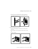
Page 129: ...r reconnect the telephone line to the wall outlet and the server 6 Secure the drawer in the rack a Slide the drawer into the rack b Locate the screws that you removed in step 3 on page 58 c Insert the...

Page 130: ...the pin on the server b Press the flange on the top edge and slide the door over the pin c Release the flange d Close and lock the door Flange What to do next When you have completed installing the c...

Page 131: ...uctions that come with the option to prepare it for installation Adding a Hot Swap Storage Expansion Enclosure The IBM PC Server Enterprise Expansion Enclosure is one of several SCSI storage enclosure...

Page 132: ...lan to attach an external SCSI device you must order an additional SCSI cable That is to use an external device with the PC Server 325 you must connect it to the external SCSI connector using a SCSI c...

Page 133: ...nectors Expansion Slots Ethernet Connectors Keyboard Connector Mouse Connector Monitor Connector Drawer model Infrared Connector Power Connector SCSI Knockout Parallel Connector Serial Connectors Expa...

Page 134: ...l See the instructions that come with the option to determine if device drivers are required and if so how to install them If you do not need to install any device drivers or update the system configu...

Page 135: ...mentation that comes with your option for information about installing any required device drivers Notes 1 If you remove a SCSI device the server might not recognize any SCSI devices that are still co...

Page 136: ...Updating the Server Configuration 122 PC Server 325 User s Handbook...

Page 137: ...Codes 126 Test Programs 126 Types of Error Messages 127 Troubleshooting 128 Option Diskettes 128 About the Test Programs 129 Using the PC Server Diagnostic Diskette 129 Using the Main Menu 129 Program...

Page 138: ...em for Damage 189 After Dropping It 189 After Spilling Liquid on It 190 Installing Additional Test Programs 191 Using the Utility Programs 194 Formatting Diskettes 194 Using the File Editor 194 Resolv...

Page 139: ...of tests to check the operation of the system and some options This series of tests is called the power on self test or POST POST does the following Checks some basic system board operations Checks th...

Page 140: ...es that POST detected an error For more information on beep codes see Beep Codes on page 185 Test Programs The PC Server Diagnostic Diskette contains the QAPlus PRO test programs developed by DiagSoft...

Page 141: ...usage device drivers and so on Utility Programs The utility programs include a text editor and a diskette formatter Types of Error Messages Error messages indicate that a problem exists they are not...

Page 142: ...s refer to the information that comes with your software package Troubleshooting The charts in Troubleshooting Charts on page 176 list symptoms of problems for example a symptom might be the mouse is...

Page 143: ...c Diskette into the diskette drive then turn on the system Or if the system is turned on already press Ctrl Alt Del The system begins POST If a power on or administrator password is set the system pro...

Page 144: ...formation For more information about the options available see Test Options on page 138 System Info When you select this choice from the Main Menu the System Info Menu appears From the System Info Men...

Page 145: ...r down Up Arrow Moves the cursor up F1 Displays the appropriate Help information Use the Up Arrow or Down Arrow key to scroll through the information Pressing F1 from within a Help screen provides a h...

Page 146: ...it number only used in the Test Module menu and on the Test Group screens Displays the previous logical unit number only used in the Test Module menu and on the Test Group screens Using the Command Li...

Page 147: ...sufficient memory available to load all of the test programs simultaneously or if you want to test specific test groups The valid test groups are LPT Parallel port COM Serial ports FDU Diskette drive...

Page 148: ...the diagnostic programs do not load To suspend IntruderAlert and continue loading the diagnostic programs press Esc The Test Group Window When you select Quick Tests or Module Tests from the Diagnost...

Page 149: ...elp F2 Log F10 Local Menu CPU IC Data Paths Interrupt Controllers Interval Timer Refresh Interrupt CMOS RAM Clock Calendar DMA Transfer NPU Speaker EISA Bus EISA ISP CPU Pentium Pro NPU Internal BIOS...

Page 150: ...off When you have selected a test a diamond appears next to the selection Attention An asterisk directly adjacent to an item indicates that running that test might damage your data Make sure to back...

Page 151: ...ess Enter Creating Test Scripts Scripting allows you to select specific groups of tests testing parameters and options You can then save your selections for later use as a test script To set up a test...

Page 152: ...al test basis Therefore if you select tests A B and C and the Lap Count is set to 3 the test sequence is ABC ABC ABC Pause Control You can choose to have the test programs pause between test modules a...

Page 153: ...he Test Log file The test programs automatically assign the extension LOG to the file if you do not specify a file name extension The file is stored in ASCII text format You can then examine the file...

Page 154: ...ler This diagnostic diskette includes the LANAID utility program Backing Up the Ethernet Diagnostic Diskette Use an operating system command such as the DOS DISKCOPY command to make a complete backup...

Page 155: ...can result in two types of error messages POST error messages appear when during startup POST finds problems with the hardware or detects a change in the hardware configuration Diagnostic error messag...

Page 156: ...ter 2 Configuring Your Server 2 If a password prompt appears with a POST message type the administrator or power on password then press Enter POST Message Description E100 E101 POST detected an invali...

Page 157: ...n A device has been removed or disconnected from a cable A device is failing and is no longer recognized by the server as being installed An external device is not turned on An invalid checksum is det...

Page 158: ...ing the VPD Action Have the system serviced 175 A hardware error occurred Action Have the system serviced 176 The server cover has been removed improperly Action Check for indications that the server...

Page 159: ...sing the Configuration Setup Utility Main Menu 186 A system board or hardware error occurred Action Have the system serviced 187 VPD serial number not set Action Have the system serviced 188 System ID...

Page 160: ...ust connected a new mouse or other pointing device turn the server off and disconnect that device Wait at least 5 seconds and then turn the server on If the error message goes away replace the device...

Page 161: ...rial printer or other serial device attached to your server verify that the serial cable is connected correctly If it is use the following procedure 1 Turn off the server 2 Disconnect the serial cable...

Page 162: ...ol 1801 A PCI adapter has requested memory resources that are not available Action 1 Make sure the PCI adapter and all other adapters are set correctly in the Configuration Setup utility programs If t...

Page 163: ...mory resource settings are correct the PCI adapter might be defective 1804 A PCI adapter has requested a memory address that is not available Action If all memory addresses are being used you might ne...

Page 164: ...8603 A failure occurred during testing of the pointing device mouse and pointing device controller This error can be caused by the addition or removal of a pointing device or by a failing system boar...

Page 165: ...ive startup sequence see Start Options on page 32 If the drive sequence is correct run the diagnostics to verify that the hard disk is functioning correctly If there is a problem with the hard disk su...

Page 166: ...improperly installed cable A defective cable Action Verify that The external SCSI devices are turned on External SCSI devices must be turned on before the system The cables for all external SCSI devic...

Page 167: ...vell NetWare server ODI driver The explanation and recommended action are included with each message PCNTNW NW 026 The MSM is unable to parse a required custom keyword Explanation The user entered an...

Page 168: ...new board could not be found Action If you installed an IBM Ethernet adapter make sure the adapter is seated properly Also check the I O settings of the board with the settings supplied to the drive P...

Page 169: ...tem Action Check the version of Netware Operating System Make sure that this driver is correct for the version of Netware that you are using Restart the server PCNTNW NW 078 The firmware file cannot b...

Page 170: ...hout an HSM routine Explanation The driver needs a Hardware Support Module routine before it can schedule an interrupt time call back Action Restart the server If the error recurs call for service PCN...

Page 171: ...at the IO address specified in the NET CFG file Action Verify that the IO Address in the NET CFG file matches with the board Otherwise remove the PORT keyword from the NET CFG file PCNTNW NW 167 PCI...

Page 172: ...None PCNTW DOS 4 A TSR is loaded above the PCNTNW MLID Explanation You tried to unload the PCNTNW MLID from memory but the PCNTNW MLID detected another Terminate and Stay Resident TSR program loaded...

Page 173: ...When two or more of the same type of Ethernet controllers are installed in the server an associated PCNTNW MLID section heading must be specified in the NET CFG file Action Create a NET CFG file and a...

Page 174: ...a newer version PCNTNW DOS 15 The frame type is already activated for frame string The NET CFG entry has been ignored Explanation Two FRAME keywords under the same main section heading specified the s...

Page 175: ...e address The PCNTNW MLID modified and corrected the address Action Verify the node address entries in the NET CFG file PCNTNW DOS 50 The board cannot be found Explanation The Ethernet controller is e...

Page 176: ...per is set to the default enable position Go to Running the Ethernet Diagnostics on page 140 to run the diagnostic utility PCNTNW DOS 65 Device not found at IOADDRESS Explanation The device was not fo...

Page 177: ...add the MLID Protocol ID Explanation The PCNTNW MLID could not register the specified Protocol ID Action Edit the NET CFG file and correct the protocol information PCNTNW OS2 22 Could not allocate me...

Page 178: ...64 The device was not found Explanation The driver cannot find the Ethernet contoller in the server Action Verify that the Ethernet enable jumper is set to the default enable position Go to About the...

Page 179: ...cating buffers Explanation The driver could not allocate the requested buffers Action Check your system configuration Edit the PROTOCOL INI file to reduce the number of Txbuffers and Rxbuffers specifi...

Page 180: ...umper is set to the default enable position 2 If the problem persists go to About the Test Programs on page 129 to run the diagnostic utility 3 Call for service PCNTND DOS 21 Board failed checksum tes...

Page 181: ...ry for PCI device Explanation The Ethernet controller does not require a DMA setting Action Remove the DMA setting in PROTOCOL INI PCNTNW DOS 32 IRQ number is already in use by another PCNET device Ex...

Page 182: ...already in use by another device Explanation The specified IRQ is specified by another device Action Modify the IRQ setting in the setup dialog box PCNTN3 18 PCI scan specified device not found Explan...

Page 183: ...yntax If the command is in the AUTOEXEC NET file edit the file to correct the syntax The only parameters that should be included are PCNTPK and BUSTYPE PCI1 PCNTPK DOS 2 Unable to reset the PCnet devi...

Page 184: ...1 Verify that the Ethernet enable jumper is set to the default enable position 2 Go to About the Test Programs on page 129 to run the diagnostic utility PCNTPK DOS 8 INT packet_int_no should be in th...

Page 185: ...r is at segment xxxx Explanation The memory address where the packet driver is loaded is xxxx Action None Packet interrupt number xxxx Explanation The interrupt number used by the packet driver is xxx...

Page 186: ...nfiguration Setup utility programs or run netconfig to match the hardware settings pntO 6 Cannot allocate memory for the adapter during an interrupt Please check your Streams parameters Explanation On...

Page 187: ...ms on page 129 to run the diagnostic utility pntO 15 No more devices to open Explanation The SunSoft Solaris driver cannot find any more Ethernet controllers Action Perform the following steps 1 Verif...

Page 188: ...rform the following steps 1 Modify your hardware settings 2 Run netconfig to search for another Ethernet controller pnt0 22 add_intr_handler failed Out of range IPL Explanation The IRQ specified or fo...

Page 189: ...lete the DMA parameter pnt0 29 The IRQ number is already in use by another Explanation The IBM PCI Ethernet adapter Explanation The specified IO address is already in use by pnt0 31 IO address is not...

Page 190: ...CD is not working properly Clean the CD by wiping it with a soft lint free cloth from the center of the CD to the outer edge Do not clean in a circular pattern This can cause loss of data If this doe...

Page 191: ...e have the system serviced Monitor Self Tests Action Some IBM monitors have their own self tests If you suspect a problem with your monitor refer to the information supplied with the monitor for adjus...

Page 192: ...s might cause unpredictable problems 3 An enhanced monitor cable with additional shielding is available for the 9521 and 9527 monitors See your IBM reseller or IBM marketing representative for informa...

Page 193: ...t working This causes the system to overheat and shut down 3 The last external device in each SCSI chain is terminated correctly See your SCSI documentation If the items above are correct have the sys...

Page 194: ...the device serviced Memory Problems Action The amount of memory displayed is less than the amount of memory installed Verify that 1 The memory module kits are seated properly 2 You have installed the...

Page 195: ...he system For more information see your SCSI documentation If the problem recurs have the system serviced An IBM option that was just installed does not work Verify that 1 The option is designed for t...

Page 196: ...d 4 The infrared device drivers have been properly installed 5 Nothing is blocking the infrared transceiver If the items above are correct have the system serviced Printer Problems Action The printer...

Page 197: ...Refer to the information that comes with the software to verify memory requirements Note If you have just installed an adapter or memory you might have a memory address conflict 2 The software is des...

Page 198: ...he connector see Installing Adapters on page 63 You installed the correct network cable If you need information about selecting the correct cable contact your IBM marketing representative or your IBM...

Page 199: ...cable is connected to the network adapter Make sure that your PCI system BIOS is current Reseat the network adapter see Installing Adapters on page 63 The network adapter stopped working without appar...

Page 200: ...ed Interrupt vector loading is in progress Keyboard controller test is in progress or has failed CMOS power failure and checksum checks are in progress CMOS configuration information validation is in...

Page 201: ...rver successfully completes POST your server might contain a defective system board a defective speaker or a disconnected speaker One Short Beep If this occurs after your server successfully completes...

Page 202: ...he server system board and an optional video adapter have failed This beep combination might also indicate that your server system board contains a failing component One Long and Three Short Beeps Thi...

Page 203: ...suffer any damage CAUTION Observe all safety and electrostatic precautions listed in this book to avoid personal injury or damage to your system If the system does not work correctly turn it off and...

Page 204: ...plug it in and turn on the system If it does not work correctly have the keyboard serviced If liquid gets inside the monitor 1 Turn off the monitor 2 Turn off the system 3 Unplug the monitor from the...

Page 205: ...tion of the test to be run Command line parameters to be passed to the program identified in the first item of this list The PC Server Diagnostic Diskette includes a sample file called SAMPLE CFG The...

Page 206: ...ou have designated to contain the QA files that directory must be listed in the PATH section of the AUTOEXEC BAT 4 You can use a CFG file other than USERDIAG CFG if you use the command line USRCONFIG...

Page 207: ...ine Modem Generic 1 Generic 2 CMD 1 CMD 2 CMD 3 The diagnostic program automatically assigns a test number to each test The test numbers start at 201 and continue upward as needed The numbers follow 2...

Page 208: ...he file editor allows you to modify text files By modifying files such as your AUTOEXEC BAT or CONFIG SYS files you can improve the test system s performance and eliminate unnecessary lines of informa...

Page 209: ...To move an active marked block of text first press F6 while the cursor is within the active block Then move the cursor to the new location where the active block is to be moved and press F6 again If t...

Page 210: ...y address configuration conflicts might occur Resolving Memory Address Conflicts The Configuration Setup utility programs might change the memory address space used by some hardware options If this ha...

Page 211: ...to video read only memory ROM You can use the Configuration Setup utility program to view or change the current setting for video ROM If the SVGA or EMM386 device driver is causing the memory address...

Page 212: ...Resolving Configuration Conflicts 198 PC Server 325 User s Handbook...

Page 213: ...n that contains troubleshooting procedures and explanations of error messages For troubleshooting and error information about your PC Server 325 see Chapter 4 Solving Problems on page 123 If you suspe...

Page 214: ...ions Multimedia The IBM PC Company Bulletin Board System BBS can be reached 24 hours a day 7 days a week Modem speeds of up to 14400 baud are supported Long distance telephone charges might apply To a...

Page 215: ...ng system compatibility tests The following is a sample of the information available at http www pc ibm com servers on the World Wide Web A listing of products that have been tested for compatibility...

Page 216: ...wing Setting up your server and IBM monitor Installing and setting up IBM options purchased from IBM or an IBM reseller 60 day preinstalled operating system support Arranging for service on site or ca...

Page 217: ...e information or to register for International Warranty Service in the U S or Canada call 1 800 497 7426 Purchasing Additional HelpWare Services During and after the warranty period you can purchase a...

Page 218: ...ent package or as an annual contract with a 10 incident limit For more information about purchasing Network and Server Support see Ordering Support Line Services Ordering Support Line Services Enhance...

Page 219: ...gh Friday The premium upgrade provides 4 hour average response 24 hours a day 7 days a week On site service to premium on site service If your warranty provides for on site service you can upgrade to...

Page 220: ...ations are available for purchase from IBM For a list of publications available in your country In the U S Canada and Puerto Rico call 1 800 879 2755 In other countries contact your IBM reseller or IB...

Page 221: ...processor Two Pin Jumper Blocks Covering both pins with a jumper defines one function of the jumper block To change the function of the jumper block cover one pin only or remove the jumper entirely To...

Page 222: ...he bottom of the jumper with one of the pins on the pin block and then slide the jumper onto that pin only 4 Reinstall the server cover and connect the cables see Completing the Installation on page 1...

Page 223: ...server To change a jumper s position for a three pin jumper block 1 Turn off the server then disconnect the server power cord 2 Remove the server cover 3 Lift the jumper straight off the pin block 4...

Page 224: ...er J26 External SCSI Termination Jumper J29 Video Enable Jumper J25 Power On Password Jumper J12 System Management Enable Jumper J49 Flash Write Protect Jumper J30 The following table provides the sys...

Page 225: ...example if you install a SCSI adapter and plan to connect all drives to it By disabling the system board SCSI controller you free system resources J29 External SCSI termination Use the default jumper...

Page 226: ...hen you restart the server POST proceeds without prompting for the password for this startup only Start the Configuration Setup utility programs and set a new power on password Before you begin Read E...

Page 227: ...er 3 Replace the server cover and reconnect all external cables and power cords see Completing the Installation on page 111 if you need additional information 4 Use the Configuration Setup utility pro...

Page 228: ...the location of the jumpers on the processor board Table 3 on page 215 contains the identifiers and descriptions of these jumpers PMC Frequency Selection Jumper Clock Ratio Jumper Clock Frequency J30...

Page 229: ...n performance Attention If the microprocessor bus to core ratio is incorrect system board components will overheat and component damage can occur Be sure that the microprocessor bus to core ratio jump...

Page 230: ...ssor that you installed Table 3 Page 2 of 2 Defining Microprocessor Operating Parameters Identifier Default Jumper Position Description J9 J10 J12 Reserved Table 4 Frequency Parameters Speed in MHz Mu...

Page 231: ...er The server serial number is also located on the front bezel On the tower model the identification numbers are located near the bottom of the front bezel On the drawer model the model number is loca...

Page 232: ...hem in case you need extra space to write new values later when you update your system s configuration Record the types and SCSI IDs for drives or devices attached to your server in the following tabl...

Page 233: ...he same cache size and type and the same clock speed as the primary microprocessor System Information Product Data Flash EEPROM Revision Level BIOS Date PCI Routing Planar SCSI IRQ IRQ15 Planar Ethern...

Page 234: ...led Cache Type Write Back Cache Size Video BIOS Caching Enabled Video Buffer Caching Disabled Option ROM Caching Disabled ROM Shadowing F0000h FFFFFh System BIOS Enabled E0000h EFFFFh System BIOS Enab...

Page 235: ...or J4 32 MB Kit 64 MB Kit 128 MB Connector J5 32 MB Kit 64 MB Kit 128 MB Total Memory Record expansion slot configuration information for your server in the following table Table 9 Expansion Slot Conf...

Page 236: ...I Termination Jumper J29 External SCSI Connector PCI Connectors Video Enable Jumper J25 Video Connector Processor Board Connector Power On Password Jumper J12 System Management Enable Jumper J49 C2 Se...

Page 237: ...Microprocessor Connector Secondary Voltage Regulator Module Connector Reserved Memory Connectors Secondary Microprocessor Connector Primary Microprocessor Fan Connector J22 Secondary Microprocessor Fa...

Page 238: ...Installed Device Records 224 PC Server 325 User s Handbook...

Page 239: ...ed in a 10BASE T link segment do not require grounding However all of the devices connected to the cables must be grounded If your server comes with an Ethernet interface cable you must install it to...

Page 240: ...link segments The following figure illustrates the RJ 45 connector 10BASE T UTP Cable RJ 45 Modular Plug Connector 1 2 3 Pins 6 Table 10 Cabling Specifications for 10BASE T Link Segments Characterist...

Page 241: ...tes the wiring in crossover cables Twisted Pair 1 2 3 6 4 5 7 8 RJ 45 Modular Connector Pin 1 1 2 2 3 4 10BASE T Cable 1 2 3 6 4 5 7 8 Pin TD TD RD RD RJ 45 Modular Connector Not used TD TD RD RD Not...

Page 242: ...port Table 11 Pin Assignments for AUI Port Pin Number Description 3 Data out 10 Data out 11 Digital ground 5 Data in 12 Data in 4 Digital ground 7 no connection 15 no connection 8 Digital ground 2 Co...

Page 243: ...e You Begin then continue at Preparing a Tower Model for Rack Installation on page 231 Before You Begin You will need the following items Flat blade screwdriver 8 inch adjustable wrench or pliers Tape...

Page 244: ...mum Altitude 2133 m 7000 ft Humidity Server on 8 to 80 Server off 8 to 80 Maximum altitude 2133 m 7000 ft Electrical Input Sine wave input 50 to 60 Hz is required Input voltage Low range Minimum 90 V...

Page 245: ...off the server Disconnect all external cables and power cords and then remove the server cover see Preparing to Add Options on page 55 1 Remove the door on the front bezel 2 Disconnect the cables fro...

Page 246: ...paring a Tower Model for Rack Installation 4 Loosen the strain relief screw located above the fan housing and between the front of the server and the drive bracket Screw 232 PC Server 325 User s Handb...

Page 247: ...gh the hole on the front of the server 6 Remove the front bezel a Remove the three screws on each side of the rear edge of the front bezel b Pull on the front bezel to remove it c Remove the speaker f...

Page 248: ...is all one color If you do not want to replace the bezel and switch cap go to step 10 on page 235 Otherwise continue with the following steps a Place the Operator LED assembly and the Operator LED bez...

Page 249: ...through the hole on the front of the server f Align the posts on the back of the bezel with the holes on the front of the server g Press the bezel into place and fasten with the six screws that you r...

Page 250: ...server then slide the front edge of the cover under the lip of the server frame c Tighten the screws in the back of the cover Captive Screws 13 Continue the installation at Installing the Drawer Mode...

Page 251: ...8 short screws 8 32 by 0 325 inch CAUTION Due to the weight of the server do not attempt to lift the server by yourself To avoid risking possible injury get another person to help you Attention To avo...

Page 252: ...angled arm of the bracket toward the middle of the server b Attach the bracket with four 8 32 by 0 325 inch screws 3 Attach the inner slide section of each slide rail to the side of the server a Pull...

Page 253: ...325 inch screws Preparing the Rack In this section you will use the following parts Two slide brackets Two outer slide rails One cable management arm Eight long screws 10 32 by 0 5 inch long Four shor...

Page 254: ...igning the holes Secure the template in place with tape b Mark the holes for the slide brackets and nut clips c Carefully remove the tape from the mounting rails and attach the template to the rear mo...

Page 255: ...he left front mounting rail Align the slide rail with the marked holes on the mounting rail b Align the holes on the bar nut with the holes on the slide rail and mounting rail c From the front of the...

Page 256: ...r nut 2 Align the holes on the bracket and bar nut assembly with the marked holes on the rear mounting rail 3 From the rear of the rack insert two long screws through the mounting rail slide bracket a...

Page 257: ...lign the slide rail with the marked holes on the mounting rail b Align the holes on the bar nut with the holes on the slide rail c From the front of the rack insert two long screws through the mountin...

Page 258: ...r of the rack align the holes on the cable arm mounting panel with the marked holes on the rear mounting rail 4 From the rear of the rack insert a long screw through holes in the cable arm bracket mou...

Page 259: ...e bays on the top 2 Align the inner slides on the sides of the server with the slide rails then slide the server onto the outer slide until the slide rails click into place Note When the drawer is ful...

Page 260: ...nitor keyboard and power cables to the corresponding connectors on the server Refer to the rack documentation for instructions 6 Attach the cables to the cable management arm using the cable ties 7 Se...

Page 261: ...y 1 0 inch long through the bezel mounting rail and nut clip 8 Attach the front door to the server a Align the bottom hinges on the front door with the pin on the server b Press the flange on the top...

Page 262: ...efer to remove the server if you are installing an internal drive in a drawer model that is installed in the bottom bay in a rack Before you begin Read Electrical Safety on page 53 and Handling Static...

Page 263: ...3 Slide the server out of the rack 4 If you have a modem or fax machine attached to the server disconnect the telephone line from the wall outlet and the server Note If you are in the United Kingdom y...

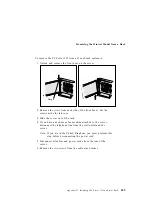
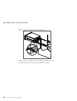
Page 264: ...el from a Rack 7 Press the safety release latch on each slide rail 8 Lift the server at a slight angle and pull it from the slide rails Then place the server on a flat nonconductive surface 250 PC Ser...

Page 265: ...evaluation and verification of operation in conjunction with other products except those expressly designated by IBM are the responsibility of the user IBM may have patents or pending patent applicati...

Page 266: ...e denoted by a double asterisk may be trademarks or service marks of others America Online America Online Inc ARCnet Datapoint Corporation CompuServe CompuServe Incorporated Intel Intel Corporation IP...

Page 267: ...tor locations 62 222 high performance 61 installation sequence 35 installing 63 ISA connector locations 62 222 locations 62 219 PCI connector locations 62 222 adapters continued removing 67 slot posit...

Page 268: ...ion 10 internal drive locations 218 beep codes POST 126 185 before you begin 52 BIOS basic input output system See also the User s Reference not installed message 152 blank screen 177 bolt down facili...

Page 269: ...e configuration 197 termination on SCSI devices 80 chassis bracket 237 circulation air 14 cleaning the monitor 14 clearances for air circulation 112 CMOS configuration data 50 comfort 13 Command Line...

Page 270: ...4 controlling access to 29 defining system security 28 exiting 34 limited menu 22 power on password 31 setting date and time 26 setting passwords 28 29 setting unattended startup 28 Configuration Setu...

Page 271: ...ation values 219 settings recording and restoring 38 values for Configuration Setup Utility 219 description 5 Attended mode 26 device drivers 42 Standby mode 26 Unattended mode 26 device adapter locat...

Page 272: ...lling in the rack 245 preparing the rack 239 preparing the server 237 removing from rack 248 status indicators 6 drive See also the User s Reference bays 77 cables 79 drive continued CD ROM 77 connect...

Page 273: ...r 163 Packet driver 169 POST 127 141 142 SCO UNIX driver 171 SCSI 152 software 129 error messages continued software generated 127 SunSoft Solaris driver 171 types 127 141 UnixWare driver 171 Ethernet...

Page 274: ...alling 116 removing 58 securing to the rack 115 front view 10 full duplex Ethernet operation function keys using 131 G general information before installing options 52 general problems 178 getting hel...

Page 275: ...es 86 test programs 191 U bolt 108 interfaces See the User s Reference intermittent problems 179 internal device records 218 219 221 drives cables 79 installing 81 purpose 77 removing 91 options insta...

Page 276: ...compliance statement ix LED light emitting diode See lights level 2 cache memory See the User s Reference lifting the system caution lighting 14 lights CD eject 5 CD ROM in use 5 diskette drive 5 Eth...

Page 277: ...ation program description 36 help information 37 Local 132 Module Tests 137 Options 138 menus continued SCSISelect Utility program 48 view or edit details 39 messages device configuration error 143 er...

Page 278: ...pace arranging 13 online help 199 online information services 200 operating system See also the User s Reference operating system continued compatibility 15 201 updating after microprocessor upgrade 1...

Page 279: ...3 42 data parity error 33 features and options 42 Interrupt Request 33 slot location 62 Pentium Pro microprocessor See the User s Reference peripheral component interconnect PCI architecture See PCI p...

Page 280: ...mory connectors 70 voltage regulator module connector 97 processor upgrade socket 97 PRODIGY 201 product compatibility 201 product continued identification numbers 217 internal and external options 21...

Page 281: ...information 52 handling static sensitive devices 54 laser compliance statement ix saving configuration settings 23 scanners SCSI 79 SCO UNIX messages 171 screen filter 14 screen flicker 177 screen bl...

Page 282: ...217 illustrated views front 10 rear 8 installing cover 111 problems 129 records 218 219 221 server continued security features passwords 28 29 startup support 16 202 support 202 tracks 111 updating c...

Page 283: ...I Ethernet Diagnostic Diskette 140 SCSISelect Utility program 47 startup drive 32 password 31 startup continued sequence 32 Startup Support 16 static sensitive devices handling 54 status indicators 4...

Page 284: ...s 138 parallel port 133 programs description 126 installing 191 scripts 137 serial port 133 specifying 133 testing continued system 129 system board 133 text editor 194 195 time setting 26 timer setti...

Page 285: ...50 configuration 19 Configuration Setup 21 diagnostic 129 194 NVRAM backup 50 SCSISelect 47 V venting of hot air 14 video See also the User s Reference changing the IRQ 33 connector location 9 222 def...

Page 286: ...write buffers CPU to PCI 33 write back See also the User s Reference configuring 33 write through configuring See also the User s Reference configuring 33 272 PC Server 325 User s Handbook...

Page 287: ......

Page 288: ...IBM Part Number 76H8831 Printed in U S A September 1996 76H8831...

Reviews: