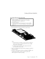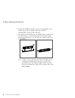
Preparing to Add Options
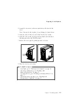
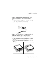
4. Loosen the six screws in the recessed holes on the back of the
cover.
Note: The screws stay in place; do not attempt to remove them.
5. Grasp the sides of the cover and slide it back a few inches.
6. Grasp the cover at the top edge with one hand, and just above
the expansion slots with the other hand.
7. Remove the cover gently, pulling upward, as shown.
Captive
Screws
8. Store the cover in a safe place.
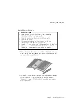
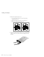
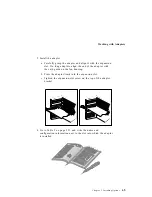
To install or remove
An adapter, go to “Working with Adapters” on page 61
A memory-module kit, go to “Working with
Memory-Module Kits” on page 70
An internal drive, go to “Working with Internal Drives” on
page 77
A microprocessor upgrade, go to “Working with
Microprocessor Upgrades” on page 97
Chapter 3. Installing Options
57
Summary of Contents for PC Server 325
Page 1: ...PC Server 325 User s Handbook IBM...
Page 6: ...vi PC Server 325 User s Handbook...
Page 10: ...Laser Compliance Statement x PC Server 325 User s Handbook...
Page 136: ...Updating the Server Configuration 122 PC Server 325 User s Handbook...
Page 212: ...Resolving Configuration Conflicts 198 PC Server 325 User s Handbook...
Page 238: ...Installed Device Records 224 PC Server 325 User s Handbook...
Page 287: ......
Page 288: ...IBM Part Number 76H8831 Printed in U S A September 1996 76H8831...

