AUI Cable
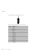
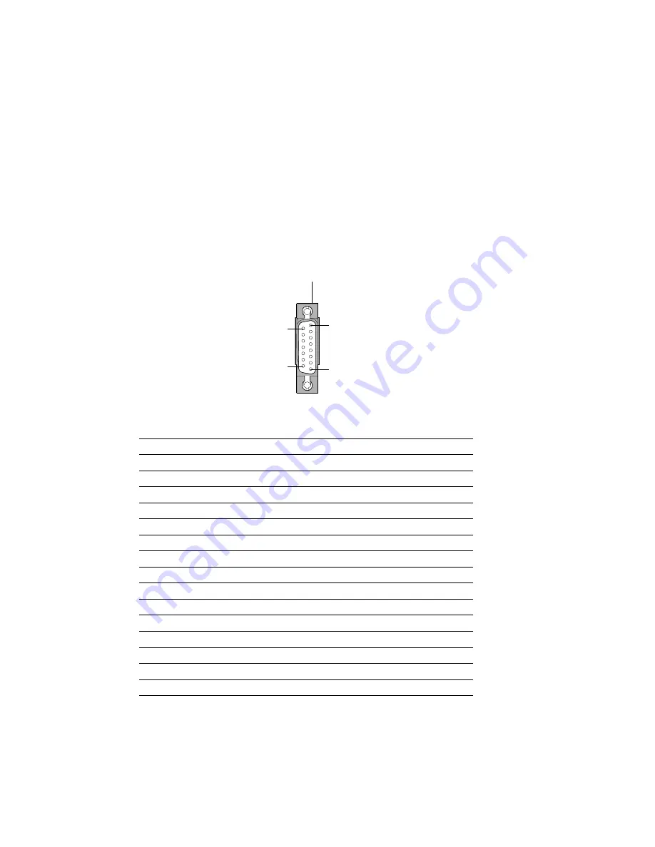
The following illustration shows the server's AUI port.
8
1
15
9
Slide
Latch
Table 11 provides the pin assignments for the server AUI port.
Table 11. Pin Assignments for AUI Port
Pin Number
Description
3
Data out +
10
Data out -
11
Digital ground
5
Data in +
12
Data in -
4
Digital ground
7
no connection
15
no connection
8
Digital ground
2
Collision in +
9
Collision in -
1
Digital ground
6
Digital ground
13
+ 12 volts
14
Digital ground
Shell
Frame ground
228
PC Server 325 User's Handbook
Summary of Contents for PC Server 325
Page 1: ...PC Server 325 User s Handbook IBM...
Page 6: ...vi PC Server 325 User s Handbook...
Page 10: ...Laser Compliance Statement x PC Server 325 User s Handbook...
Page 136: ...Updating the Server Configuration 122 PC Server 325 User s Handbook...
Page 212: ...Resolving Configuration Conflicts 198 PC Server 325 User s Handbook...
Page 238: ...Installed Device Records 224 PC Server 325 User s Handbook...
Page 287: ......
Page 288: ...IBM Part Number 76H8831 Printed in U S A September 1996 76H8831...

