


en06000608_ansi.vsd
I
F
V
S
V
’
M
=
H
V
L
H
V
S
With bypassed
capacitor
I
F
H
V
L
V
S
H
V
C
V
M
H
V
S
With inserted
capacitor
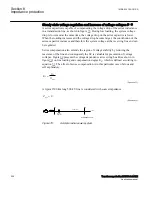
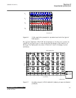
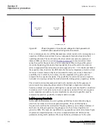
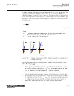
ANSI06000608 V1 EN-US
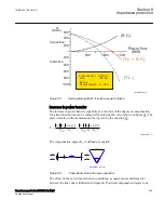
Figure 95:
Phasor diagrams of currents and voltages for the bypassed and
inserted series capacitor during current inversion
It is a common practice to call this phenomenon current inversion. Its consequences on
operation of different protections in series compensated networks depend on their
operating principle. The most known effect has current inversion on operation of
distance IEDs (as shown in section
cannot be used for the protection of series compensated lines with possible current
inversion. Equation
shows also big dependence of possible current inversion on
series compensated lines on location of series capacitors. X
L1
= 0 for faults just behind
the capacitor when located at line IED and only the source impedance prevents current
inversion. Current inversion has been considered for many years only a theoretical
possibility due to relatively low values of source impedances (big power plants)
compared to the capacitor reactance. The possibility for current inversion in modern
networks is increasing and must be studied carefully during system preparatory studies.
The current inversion phenomenon should not be studied only for the purposes of
protection devices measuring phase currents. Directional comparison protections,
based on residual (zero sequence) and negative sequence currents should be considered
in studies as well. Current inversion in zero sequence systems with low zero sequence
source impedance (a number of power transformers connected in parallel) must be
considered as practical possibility in many modern networks.
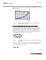
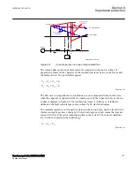
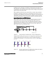
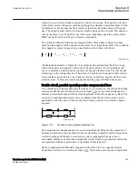
Low frequency transients
SEMOD168320-220 v2
Series capacitors introduce in power systems oscillations in currents and voltages,
which are not common in non-compensated systems. These oscillations have
frequencies lower than the rated system frequency and may cause delayed increase of
fault currents, delayed operation of spark gaps as well as, delayed operation of
protective IEDs. The most obvious difference is generally seen in fault currents. Figure
presents a simplified picture of a series compensated network with basic line
parameters during fault conditions. We study the basic performances for the same
Section 8
1MRK 504 163-UUS A
Impedance protection
218
Transformer protection RET670 2.2 ANSI
Application manual
Summary of Contents for RELION RET670
Page 1: ...RELION 670 SERIES Transformer protection RET670 Version 2 2 ANSI Application manual ...
Page 2: ......
Page 48: ...42 ...
Page 64: ...58 ...
Page 74: ...68 ...
Page 104: ...98 ...
Page 194: ...188 ...
Page 518: ...512 ...
Page 618: ...612 ...
Page 648: ...642 ...
Page 666: ...660 ...
Page 672: ...666 ...
Page 682: ...676 ...
Page 844: ...838 ...
Page 868: ...862 ...
Page 956: ...950 ...
Page 964: ...958 ...
Page 1004: ...998 ...
Page 1014: ...1008 ...
Page 1015: ...1009 ...


