7.2.4.1
Configuration
M13076-5 v4
The configuration is done in the Application Configuration tool.
7.2.4.2
Settings of protection function
M13076-10 v6
Operation
: The operation of the high impedance differential function can be switched
Enabled
or
Disabled
.
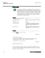
AlarmPickup
: Set the alarm level. The sensitivity can roughly be calculated as a certain
percentage of the selected Trip level. A typical setting is 10% of
TripPickup.
This
alarm stage can be used for scheme CT supervision.
tAlarm
: Set the time delay for the alarm. A typical setting is 2-3 seconds.
TripPickup
: Set the trip level according to the calculations (see examples below for a
guidance). The level is selected with margin to the calculated required voltage to
achieve stability. Values can be within 20V - 400V range dependent on the application.
R series
: Set the value of the used stabilizing series resistor. Calculate the value
according to the examples for each application. Adjust the resistor as close as possible
to the calculated value. Measure the value achieved and set this value for this
parameter.
The value shall always be high impedance. This means for example, for
1A circuits say bigger than 400 ohms (400 VA) and for 5 A circuits say
bigger than 100 ohms (2500 VA). This ensures that the current will
circulate and not go through the differential circuit at through faults.
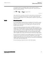
That the settings of U>Alarm, U>Trip and SeriesResistor must be
chosen such that both U>Alarm/SeriesResistor and U>Trip/
SeriesResistor are >4% of IRated of the used current input. Normally
the settings shall also be such that U>Alarm/SeriesResistor and
U>Trip/SeriesResistor both gives a value <4*IRated of the used current
input. If not, the limitation in how long time the actual current is
allowed to persist not to overload the current input must be considered
especially during the secondary testing.
7.2.4.3
T-feeder protection
M16850-4 v6
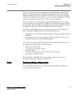
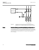
In many busbar arrangements such as breaker-and-a-half, ring breaker, mesh corner,
there will be a T-feeder from the current transformer at the breakers up to the current
1MRK 504 163-UUS A
Section 7
Differential protection
Transformer protection RET670 2.2 ANSI
167
Application manual
Summary of Contents for RELION RET670
Page 1: ...RELION 670 SERIES Transformer protection RET670 Version 2 2 ANSI Application manual ...
Page 2: ......
Page 48: ...42 ...
Page 64: ...58 ...
Page 74: ...68 ...
Page 104: ...98 ...
Page 194: ...188 ...
Page 518: ...512 ...
Page 618: ...612 ...
Page 648: ...642 ...
Page 666: ...660 ...
Page 672: ...666 ...
Page 682: ...676 ...
Page 844: ...838 ...
Page 868: ...862 ...
Page 956: ...950 ...
Page 964: ...958 ...
Page 1004: ...998 ...
Page 1014: ...1008 ...
Page 1015: ...1009 ...


