


en05000220_ansi.vsd
R
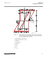
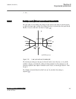
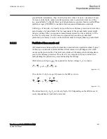
Zm
LdAngle
LdAngle
LdAngle
LdAngle
RLdFwd
RLdRev
ZL
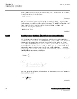
ANSI05000220 V1 EN-US
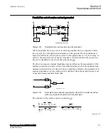
Figure 124:
Characteristic for zone measurement for a long line
8.3.2.6
Parallel line application with mutual coupling
M17048-417 v2
General
M17048-567 v3
Introduction of parallel lines in the network is increasing due to difficulties to get
necessary area for new lines.
Parallel lines introduce an error in the measurement due to the mutual coupling
between the parallel lines. The lines need not be of the same voltage in order to
experience mutual coupling, and some coupling exists even for lines that are separated
by 100 meters or more. The mutual coupling does influence the zero sequence
impedance to the fault point but it does not normally cause voltage inversion.
It can be shown from analytical calculations of line impedances that the mutual
impedances for positive and negative sequence are very small (< 1-2%) of the self
impedance and it is a practice to neglect them.
From an application point of view there exists three types of network configurations
(classes) that must be considered when making the settings for the protection function.
The different network configuration classes are:
1MRK 504 163-UUS A
Section 8
Impedance protection
Transformer protection RET670 2.2 ANSI
265
Application manual
Summary of Contents for RELION RET670
Page 1: ...RELION 670 SERIES Transformer protection RET670 Version 2 2 ANSI Application manual ...
Page 2: ......
Page 48: ...42 ...
Page 64: ...58 ...
Page 74: ...68 ...
Page 104: ...98 ...
Page 194: ...188 ...
Page 518: ...512 ...
Page 618: ...612 ...
Page 648: ...642 ...
Page 666: ...660 ...
Page 672: ...666 ...
Page 682: ...676 ...
Page 844: ...838 ...
Page 868: ...862 ...
Page 956: ...950 ...
Page 964: ...958 ...
Page 1004: ...998 ...
Page 1014: ...1008 ...
Page 1015: ...1009 ...


