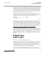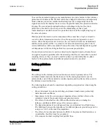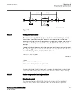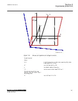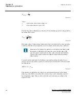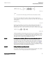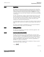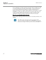
When the calculation of XFw gives a negative value the zone 1 must be
permanently blocked.
For protection on non compensated lines facing series capacitor on next line. The
setting is thus:
•
X1
is set to (XLine-XC · K) · p/100.
•
K
equals side infeed factor at next busbar.
When the calculation of XFw gives a negative value the zone 1 must be
permanently blocked.
Fault resistance
SEMOD168247-201 v2
The resistive reach is, for all affected applications, restricted by the set reactive reach
and the load impedance and same conditions apply as for a non-compensated network.
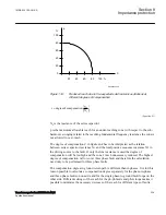
However, special notice has to be taken during settings calculations due to the ZnO
because 50% of capacitor reactance appears in series with resistance, which
corresponds to approximately 36% of capacitor reactance when the line current equals
two times the protective current level. This information has high importance for setting
of distance protection IED reach in resistive direction, for phase to ground- fault
measurement as well as, for phase-to-phase measurement.
Overreaching zone 2
SEMOD168247-211 v2
In series compensated network where independent tripping zones will have reduced
reach due to the negative reactance in the capacitor and the sub-harmonic swinging the
tripping will to a high degree be achieved by the communication scheme.
With the reduced reach of the under-reaching zones not providing effective protection
for all faults along the length of the line, it becomes essential to provide over-reaching
schemes like permissive overreach transfer trip (POTT) or blocking scheme can be
used.
Thus it is of great importance that the zone 2 can detect faults on the whole line both
with the series capacitor in operation and when the capacitor is bridged (short
circuited). It is supposed also in this case that the reactive reach for phase-to-phase and
for phase-to-ground faults is the same. The X1Fw, for all lines affected by the series
capacito, are set to:
•
X1
>= 1,5 · XLine
Section 8
1MRK 504 163-UUS A
Impedance protection
242
Transformer protection RET670 2.2 ANSI
Application manual
Summary of Contents for RELION RET670
Page 1: ...RELION 670 SERIES Transformer protection RET670 Version 2 2 ANSI Application manual ...
Page 2: ......
Page 48: ...42 ...
Page 64: ...58 ...
Page 74: ...68 ...
Page 104: ...98 ...
Page 194: ...188 ...
Page 518: ...512 ...
Page 618: ...612 ...
Page 648: ...642 ...
Page 666: ...660 ...
Page 672: ...666 ...
Page 682: ...676 ...
Page 844: ...838 ...
Page 868: ...862 ...
Page 956: ...950 ...
Page 964: ...958 ...
Page 1004: ...998 ...
Page 1014: ...1008 ...
Page 1015: ...1009 ...


