


With these factors, TR1ATCC (90) or TR8ATCC (90) adjusts the value of the set
voltage
Vset
according to the following formula:
2
L
a
ci
I
Vsetadjust Vset S
S
I Base
=
+ ×
+
EQUATION1978-ANSI V2 EN-US
(Equation 507)
V
set, adjust
Adjusted set voltage in per unit
VSet
Original set voltage: Base quality is V
n2
S
a
Automatic load voltage adjustment factor, setting
VRAuto
I
L
Load current
I2Base
Rated current, LV winding
S
ci
Constant load voltage adjust. factor for active input
i (corresponding to
LVAConst1, LVAConst2, LVAConst3 and LVAConst4)
It shall be noted that the adjustment factor is negative in order to decrease the load
voltage and positive in order to increase the load voltage. After this calculation V
set,
adjust
will be used by TR1ATCC (90) or TR8ATCC (90) for voltage regulation instead
of the original value
Vset
. The calculated set point voltage V
set, adjust
is shown on the
local HMI as a service value under
Main menu/Test/Function status/Control/
TransformerVoltageControl(ATCC,90)/TR1ATCC:x/TR8ATCC:x
.
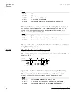
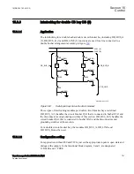
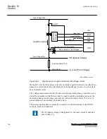
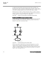
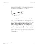
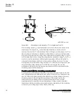
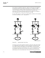
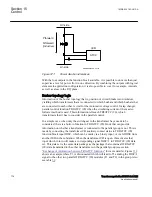
Automatic control of parallel transformers
SEMOD159053-135 v5
Control of parallel transformers means control of two or more power transformers
connected to the same busbar on the LV side and in most cases also on the HV side.
Special measures must be taken in order to avoid a runaway situation where the tap
changers on the parallel transformers gradually diverge and end up in opposite end
positions.
Three alternative methods can be used for parallel control with the Automatic voltage
control for tap changer, single/parallel control TR8ATCC (90):
•
master-follower method
•
reverse reactance method
•
circulating current method
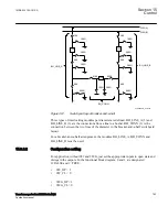
In order to realize the need for special measures to be taken when controlling
transformers in parallel, consider first two parallel transformers which are supposed to
be equal with similar tap changers. If they would each be in automatic voltage control
for single transformer that is, each of them regulating the voltage on the LV busbar
individually without any further measures taken, then the following could happen.
Section 15
1MRK 504 163-UUS A
Control
764
Transformer protection RET670 2.2 ANSI
Application manual
Summary of Contents for RELION RET670
Page 1: ...RELION 670 SERIES Transformer protection RET670 Version 2 2 ANSI Application manual ...
Page 2: ......
Page 48: ...42 ...
Page 64: ...58 ...
Page 74: ...68 ...
Page 104: ...98 ...
Page 194: ...188 ...
Page 518: ...512 ...
Page 618: ...612 ...
Page 648: ...642 ...
Page 666: ...660 ...
Page 672: ...666 ...
Page 682: ...676 ...
Page 844: ...838 ...
Page 868: ...862 ...
Page 956: ...950 ...
Page 964: ...958 ...
Page 1004: ...998 ...
Page 1014: ...1008 ...
Page 1015: ...1009 ...


