•
tReset
: Interval of time since the last pole-slip detected, when the Out-of-step
protection is reset. If there is no more pole slips detected under the time interval
specified by
tReset
since the previous one, the function is reset. All outputs are set
to 0 (
FALSE
). If no pole slip at all is detected under interval of time specified by
tReset
since the pickup signal has been set (for example a stable case with
synchronism retained), the function is as well reset, which includes the pickup
output signal (
PICKUP
), which is reset to 0 (
FALSE
) after
tReset
interval of time
has elapsed. However, the measurements of analogue quantities such as R, X, P, Q,
and so on continue without interruptions. Recommended setting of
tReset
is in the
range of 6 to 12 seconds.
•
NoOfSlipsZ1
: Maximum number of pole slips with centre of electromechanical
oscillation within zone 1 required for a trip. Usually,
NoOfSlipsZ1
=
1
.
•
NoOfSlipsZ2
: Maximum number of pole slips with centre of electromechanical
oscillation within zone 2 required for a trip. The reason for the existence of two
zones of operation is selectivity, required particularly for successful islanding. If
there are several pole slip (out-of-step) relays in the power system, then selectivity
between relays is obtained by the relay reach (for example zone 1) rather then by
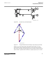
time grading. In a system, as in Table
, the number of allowed pole slips in zone
2 can be the same as in zone 1. Recommended value:
NoOfSlipsZ2
=
2
or
3
.
•
Operation
: With the setting
Operation
OOSPPAM function can be set
On/Off
.
•
OperationZ1
: Operation zone 1
Enabled
,
Disabled
. If
OperationZ1
=
Disabled
, all
pole-slips with centre of the electromagnetic oscillation within zone 1 are ignored.
Default setting =
Enabled
. More likely to be used is the option to extend zone 1 so
that zone 1 even covers zone 2. This feature is activated by the input to extend the
zone 1 (EXTZ1).
•
OperationZ2
: Operation zone 2
Enabled
,
Disabled
. If
OperationZ1
=
Disabled
, all
pole-slips with centre of the electromagnetic oscillation within zone 2 are ignored.
Default setting =
Enabled
.
•
tBreaker
: Circuit breaker opening time. Use the default value
tBreaker
=
0.000 s
if
unknown. If the value is known, then a value higher than 0.000 is specified, for
example
tBreaker
=
0.040 s
: the out-of-step function gives a trip command
approximately 0.040 seconds before the currents reach their minimum value. This
in order to decrease the stress imposed to the circuit breaker.
•
VBase
: This is the voltage at the point where the Out-of-step protection is
installed. If the protection is installed on the generator output terminals, then
VBase
is the nominal (rated) phase to phase voltage of the protected generator. All
the resistances and reactances are measured and displayed referred to voltage
VBase
. Observe that
ReverseX
,
ForwardX
,
ReverseR
, and
ForwardR
must be
given referred to
VBase.IBase
is the protected generator nominal (rated) current, if
the Out-of-step protection belongs to a generator protection scheme.
•
InvertCTCurr
: If the currents fed to the Out-of-step protection are measured on the
protected generator neutral side (LV-side) then inversion is not necessary
(
InvertCTCurr
=
Disabled
), provided that the CT’s orientation complies with ABB
recommendations, as shown in Table
. If the currents fed to the Out-of-step
1MRK 504 163-UUS A
Section 8
Impedance protection
Transformer protection RET670 2.2 ANSI
487
Application manual
Summary of Contents for RELION RET670
Page 1: ...RELION 670 SERIES Transformer protection RET670 Version 2 2 ANSI Application manual ...
Page 2: ......
Page 48: ...42 ...
Page 64: ...58 ...
Page 74: ...68 ...
Page 104: ...98 ...
Page 194: ...188 ...
Page 518: ...512 ...
Page 618: ...612 ...
Page 648: ...642 ...
Page 666: ...660 ...
Page 672: ...666 ...
Page 682: ...676 ...
Page 844: ...838 ...
Page 868: ...862 ...
Page 956: ...950 ...
Page 964: ...958 ...
Page 1004: ...998 ...
Page 1014: ...1008 ...
Page 1015: ...1009 ...


