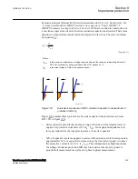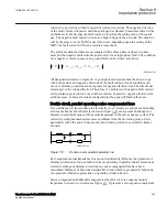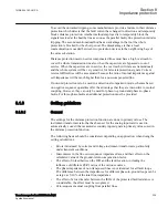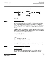
(ZMCPDIS,ZMCAPDIS, 21). This function is necessary in the protection on
compensated lines as well as all non-compensated lines connected to this busbar
(adjacent lines). All protections that can be exposed to voltage reversal must have the
special directional function, including the protections on busbar where the voltage can
be reversed by series compensated lines not terminated to this busbar.
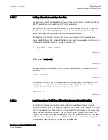
The directional function is controlled by faulty phase criteria. These criteria must
identify all forward and reverse faults that can cause voltage reversal. Setting of the
corresponding reach of the impedance measuring elements is separate for reactive and
resistive reach and independent of each other for phase-to-ground and for phase-to-
phase measurement.
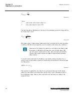
It is also necessary to consider the minimum load impedance limiting conditions:
Setting of zone 1
SEMOD168247-150 v3
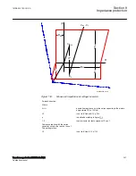
A voltage reversal can cause an artificial internal fault (voltage zero) on faulty line as
well as on the adjacent lines. This artificial fault always have a resistive component,
this is however small and can mostly not be used to prevent tripping of a healthy
adjacent line.
An independent tripping zone 1 facing a bus which can be exposed to voltage reversal
have to be set with reduced reach with respect to this false fault. When the fault can
move and pass the bus, the zone 1 in this station must be blocked. Protection further
out in the net must be set with respect to this apparent fault as the protection at the bus.
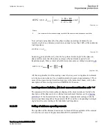
Different settings of the reach for the zone (ZMCPDIS, 21) characteristic in forward
and reverse direction makes it possible to optimize the settings in order to maximize
dependability and security for independent zone1.
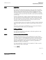
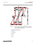
Due to the sub-harmonic oscillation swinging caused by the series capacitor at fault
conditions the reach of the under-reaching zone 1 must be further reduced. Zone 1 can
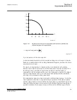
only be set with a percentage reach to the artificial fault according to the curve in
Section 8
1MRK 504 163-UUS A
Impedance protection
238
Transformer protection RET670 2.2 ANSI
Application manual
Summary of Contents for RELION RET670
Page 1: ...RELION 670 SERIES Transformer protection RET670 Version 2 2 ANSI Application manual ...
Page 2: ......
Page 48: ...42 ...
Page 64: ...58 ...
Page 74: ...68 ...
Page 104: ...98 ...
Page 194: ...188 ...
Page 518: ...512 ...
Page 618: ...612 ...
Page 648: ...642 ...
Page 666: ...660 ...
Page 672: ...666 ...
Page 682: ...676 ...
Page 844: ...838 ...
Page 868: ...862 ...
Page 956: ...950 ...
Page 964: ...958 ...
Page 1004: ...998 ...
Page 1014: ...1008 ...
Page 1015: ...1009 ...


