19
20
21
22
23
24
13
14
15
16
17
18
A
AI 07(I)
AI08 (V)
AI09 (V)
AI10(V)
AI11(V)
AI12(V)
IED
B
C
13.8
120
kV
V
1
2
3
#Not Used
13.8
120
kV
V
5
ANSI06000600-3-en.vsd
SMAI2
BLOCK
^GRP2_A (A-B)
^GRP2_B (B-C)
^GRP2_C (C-A)
^GRP2N
TYPE
AI3P
AI1
AI2
AI3
AI4
AIN
4
ANSI06000600 V3 EN-US
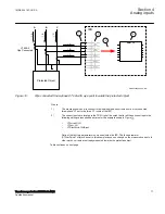
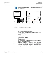
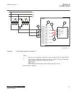
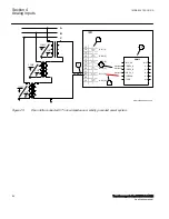
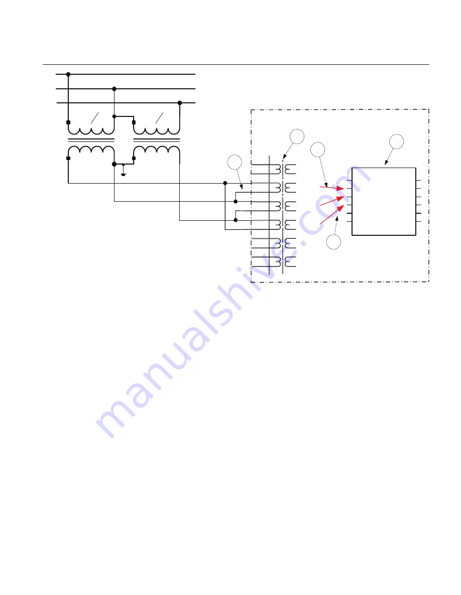
Figure 23:
A Two phase-to-phase connected VT
Where:
1)
shows how to connect the secondary side of a phase-to-phase VT to the VT inputs on the IED
2)
is the TRM where these three voltage inputs are located. It shall be noted that for these three
voltage inputs the following setting values shall be entered:
VTprim=13.8 kV
VTsec=120 V
Please note that inside the IED only ratio of these two parameters is used.
Table continues on next page
1MRK 504 163-UUS A
Section 4
Analog inputs
Transformer protection RET670 2.2 ANSI
91
Application manual
Summary of Contents for RELION RET670
Page 1: ...RELION 670 SERIES Transformer protection RET670 Version 2 2 ANSI Application manual ...
Page 2: ......
Page 48: ...42 ...
Page 64: ...58 ...
Page 74: ...68 ...
Page 104: ...98 ...
Page 194: ...188 ...
Page 518: ...512 ...
Page 618: ...612 ...
Page 648: ...642 ...
Page 666: ...660 ...
Page 672: ...666 ...
Page 682: ...676 ...
Page 844: ...838 ...
Page 868: ...862 ...
Page 956: ...950 ...
Page 964: ...958 ...
Page 1004: ...998 ...
Page 1014: ...1008 ...
Page 1015: ...1009 ...

