


Q>
: When the reactive power exceeds the value given by this setting, the output
QGTFWD will be activated after the time delay
tPower
. It shall be noticed that the
setting is given with sign, which effectively means that the function picks up for all
values of reactive power greater than the set value, similar to the functionality for
P>
.
Q<
: When the reactive power falls below the value given by this setting, the output
QLTREV will be activated after the time delay
tPower
. It shall be noticed that the
setting is given with sign, which effectively means that the function picks up for all
values of reactive power less than the set value, similar to the functionality for
P<
.
tPower
: Time delay for activation of the power monitoring output signals (PGTFWD,
PLTREV, QGTFWD and QLTREV).
Parallel control (ParCtrl)
OperationPAR
: Setting of the method for parallel operation.
OperCCBlock
: This setting enables/disables blocking if the circulating current exceeds
CircCurrLimit
.
CircCurrLimit
: Pick up value for the circulating current blocking function. The setting
is made in percent of
I2Base
.
tCircCurr
: Time delay for the circulating current blocking function.
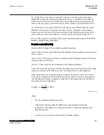
Comp
: When parallel operation with the circulating current method is used, this setting
increases or decreases the influence of the circulating current on the regulation.
If the transformers are connected to the same bus on the HV- as well as the LV-side,
Comp
can be calculated with the following formula which is valid for any number of
two-winding transformers in parallel, irrespective if the transformers are of different
size and short circuit impedance.
2
V
Comp a
100%
n p
´ D
= ´
´
´
EQUATION1984-ANSI V1 EN-US
(Equation 515)
where:
•
D
V is the deadband setting in percent.
•
n
denotes the desired number of difference in tap position between the
transformers, that shall give a voltage deviation V
di
which corresponds to the
dead-band setting.
•
p
is the tap step (in percent of transformer nominal voltage).
1MRK 504 163-UUS A
Section 15
Control
Transformer protection RET670 2.2 ANSI
799
Application manual
Summary of Contents for RELION RET670
Page 1: ...RELION 670 SERIES Transformer protection RET670 Version 2 2 ANSI Application manual ...
Page 2: ......
Page 48: ...42 ...
Page 64: ...58 ...
Page 74: ...68 ...
Page 104: ...98 ...
Page 194: ...188 ...
Page 518: ...512 ...
Page 618: ...612 ...
Page 648: ...642 ...
Page 666: ...660 ...
Page 672: ...666 ...
Page 682: ...676 ...
Page 844: ...838 ...
Page 868: ...862 ...
Page 956: ...950 ...
Page 964: ...958 ...
Page 1004: ...998 ...
Page 1014: ...1008 ...
Page 1015: ...1009 ...


