


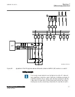

presence of heavy CT saturation. The principle is based on the CT secondary current
circulating between involved current transformers and not through the IED due to high
impedance in the measuring branch. This stabilizing resistance is in the range of
hundreds of ohms and sometimes above one kilo Ohm. When an internal fault occurs
the current cannot circulate and is forced through the measuring branch causing relay
operation.
It should be remembered that the whole scheme, its built-in components and wiring
must be adequately maintained throughout the lifetime of the equipment in order to be
able to withstand the high voltage peaks (that is, pulses) which may appear during an
internal fault. Otherwise any flash-over in CT secondary circuits or any other part of
the scheme may prevent correct operation of the high impedance differential relay for
an actual internal fault.
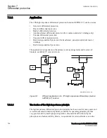
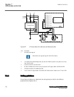
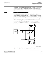
87N
en05000164_ansi.vsd
ANSI05000164 V1 EN-US
Figure 54:
Example for the high impedance restricted earth fault protection
application
For a through fault one current transformer might saturate when the other CTs still will
feed current. For such a case a voltage will be developed across the measuring branch.
1MRK 504 163-UUS A
Section 7
Differential protection
Transformer protection RET670 2.2 ANSI
159
Application manual
Summary of Contents for RELION RET670
Page 1: ...RELION 670 SERIES Transformer protection RET670 Version 2 2 ANSI Application manual ...
Page 2: ......
Page 48: ...42 ...
Page 64: ...58 ...
Page 74: ...68 ...
Page 104: ...98 ...
Page 194: ...188 ...
Page 518: ...512 ...
Page 618: ...612 ...
Page 648: ...642 ...
Page 666: ...660 ...
Page 672: ...666 ...
Page 682: ...676 ...
Page 844: ...838 ...
Page 868: ...862 ...
Page 956: ...950 ...
Page 964: ...958 ...
Page 1004: ...998 ...
Page 1014: ...1008 ...
Page 1015: ...1009 ...


