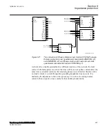
PU27PN
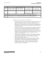
: The setting of the phase-to- ground voltage level (phase voltage) which is
used by the evaluation logic to verify that a fault exists in the phase. Normally in a
high impedance grounded system, the voltage drop is big and the setting can typically
be set to 70% of base voltage (
VBase
)
PU27PP
: The setting of the phase-to-phase voltage level (line voltage) which is used
by the evaluation logic to verify that a fault exists in two or more phases. The voltage
must be set to avoid that a partly healthy phase-to-phase voltage, for example, B-C for
a A-B fault, picks-up and gives an incorrect release of all loops. The setting can
typically be 40 to 50% of rated voltage (
VBase
) divided by √3, that is 40%.
3V0PU
: The setting of the residual voltage level (neutral voltage) which is used by the
evaluation logic to verify that an ground-fault exists. The setting can typically be 20%
of base voltage (
VBase
).
Pickup_N
: The setting of the residual current level (neutral current) which is used by
the evaluation logic to verify that a cross-country fault exists. The setting can typically
be 20% of base current (
IBase
) but the setting shall be above the maximum current
generated by the system grounding. Note that the systems are high impedance
grounded which means that the ground-fault currents at ground-faults are limited and
the occurring IN above this level shows that there exists a two-phase fault on this line
and a parallel line where the IN is the fault current level in the faulty phase. A high
sensitivity need not to be achieved as the two-phase fault level normally is well above
base current.
tIN
: The time delay for detecting that the fault is cross-country. Normal time setting is
0.1 - 0.15 s.
tVN
: The time delay for a secure VN detecting that the fault is an ground-fault or
double ground-fault with residual voltage. Normal time setting is 0.1 - 0.15 s.
tOffVN
: The VN voltage has a reset drop-off to ensure correct function without timing
problems. Normal time setting is 0.1 s
8.20
Phase preference logic PPL2PHIZ
GUID-80133640-FB3E-400C-B7FF-C2BB0AD1A045 v1
8.20.1
Identification
GUID-850E4134-E912-45EC-981E-E1A2C12A91A8 v1
Function description
IEC 61850
identification
IEC 60617
identification
ANSI/IEEE C37.2
device number
Phase preference logic
PPL2PHIZ
-
-
1MRK 504 163-UUS A
Section 8
Impedance protection
Transformer protection RET670 2.2 ANSI
495
Application manual
Summary of Contents for RELION RET670
Page 1: ...RELION 670 SERIES Transformer protection RET670 Version 2 2 ANSI Application manual ...
Page 2: ......
Page 48: ...42 ...
Page 64: ...58 ...
Page 74: ...68 ...
Page 104: ...98 ...
Page 194: ...188 ...
Page 518: ...512 ...
Page 618: ...612 ...
Page 648: ...642 ...
Page 666: ...660 ...
Page 672: ...666 ...
Page 682: ...676 ...
Page 844: ...838 ...
Page 868: ...862 ...
Page 956: ...950 ...
Page 964: ...958 ...
Page 1004: ...998 ...
Page 1014: ...1008 ...
Page 1015: ...1009 ...

