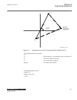
R
X
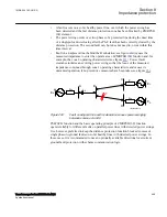
Apparent
impedance at
normal load
Z
C
Z
A
Z
B
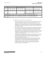
anglePhi
IEC07000015_2_en.vsd
IEC07000015 V2 EN-US
Figure 238:
Impedances to be set for pole slip protection
The setting parameters of the protection is:
Z
A
:
Line + source impedance in the forward direction
Z
B
:
The source impedance in the reverse direction
Z
C
:
The line impedance in the forward direction
AnglePhi:
The impedance phase angle
Use the following data:
UBase: 400 kV
SBase set to 1000 MVA
Short circuit power at station 1 without infeed from the protected line: 5000 MVA (assumed to a pure
reactance)
Short circuit power at station 2 without infeed from the protected line: 5000 MVA (assumed to a pure
reactance
Line impedance: 2 + j20 ohm
1MRK 504 163-UUS A
Section 8
Impedance protection
Transformer protection RET670 2.2 ANSI
473
Application manual
Summary of Contents for RELION RET670
Page 1: ...RELION 670 SERIES Transformer protection RET670 Version 2 2 ANSI Application manual ...
Page 2: ......
Page 48: ...42 ...
Page 64: ...58 ...
Page 74: ...68 ...
Page 104: ...98 ...
Page 194: ...188 ...
Page 518: ...512 ...
Page 618: ...612 ...
Page 648: ...642 ...
Page 666: ...660 ...
Page 672: ...666 ...
Page 682: ...676 ...
Page 844: ...838 ...
Page 868: ...862 ...
Page 956: ...950 ...
Page 964: ...958 ...
Page 1004: ...998 ...
Page 1014: ...1008 ...
Page 1015: ...1009 ...

