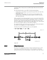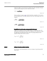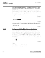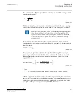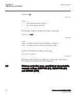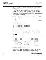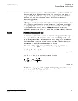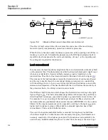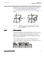
The negative-sequence voltage polarized ground directional unit compares
correspondingly I
2
with -V2.
In general the zero sequence voltage is higher than the negative sequence voltage at the
fault, but decreases more rapidly the further away from the fault it is measured. This
makes the -V
0
polarization preferable in short line applications, where no mutual
coupling problems exist.
Negative sequence polarization has the following advantages compared to zero
sequence polarization:
•
on solidly grounded systems V2 may be larger than V
0
. If the bus behind the IED
location is a strong zero-sequence source, the negative sequence voltage available
at the IED location is higher than the zero-sequence voltage.
•
negative sequence polarization is not affected by zero sequence mutual coupling
(zero sequence polarized directional elements may misoperate in parallel lines
with high zero-sequence mutual coupling and isolated zero sequence sources).
•
negative sequence polarization is less affected by the effects of VT neutral shift
(possible caused by ungrounded or multiple grounds on the supplying VT neutral)
•
no open-delta winding is needed in VTs as only 2 VTs are required (V
2
= (V
L12
- a
· V
L23
)/3)
The zero sequence current polarized ground directional unit compares zero sequence
current I0 of the line with some reference zero-sequence current, for example the
current in the neutral of a power transformer. The relay characteristic
AngleRCA
is
fixed and equals 0 degrees. Care must be taken to ensure that neutral current direction
remains unchanged during all network configurations and faults, and therefore all
transformer configurations/constructions are not suitable for polarization.
In dual polarization, zero sequence voltage polarization and zero sequence current
polarization elements function in a “one-out-of-two mode”. Typically when the zero
sequence current is high, then the zero sequence voltage is low and vice versa. Thus
combining a zero sequence voltage polarized and a zero sequence current polarized
(neutral current polarized) directional element into one element, the IED can benefit
from both elements as the two polarization measurements function in a “one-out-of-
two mode” complementing each other. In this mode, if IPOL is greater than IPOL>
setting, then only IPOL based direction is detected and UPOL based direction will be
blocked. Flexibility is also increased as zero sequence voltage polarization can be used,
if the zero sequence current polarizing source is switched out of service. When the zero
sequence polarizing current exceeds the set value for IPOL>, zero sequence current
polarizing is used. For values of zero sequence polarizing current less than the set
value for startPolCurrLevel, zero sequence voltage polarizing is used.
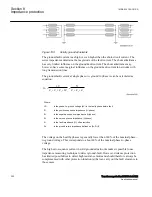
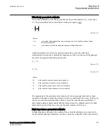
Zero-sequence voltage polarization with zero-sequence current compensation (-
V0Comp) compares the phase angles of zero sequence current I
0
with zero-sequence
Section 8
1MRK 504 163-UUS A
Impedance protection
314
Transformer protection RET670 2.2 ANSI
Application manual
Summary of Contents for RELION RET670
Page 1: ...RELION 670 SERIES Transformer protection RET670 Version 2 2 ANSI Application manual ...
Page 2: ......
Page 48: ...42 ...
Page 64: ...58 ...
Page 74: ...68 ...
Page 104: ...98 ...
Page 194: ...188 ...
Page 518: ...512 ...
Page 618: ...612 ...
Page 648: ...642 ...
Page 666: ...660 ...
Page 672: ...666 ...
Page 682: ...676 ...
Page 844: ...838 ...
Page 868: ...862 ...
Page 956: ...950 ...
Page 964: ...958 ...
Page 1004: ...998 ...
Page 1014: ...1008 ...
Page 1015: ...1009 ...

