


A
B
C
Z0m
Z0
Z0
m
-
Z0
Z0
m
-
99000038.vsd
IEC99000038 V1 EN-US
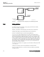
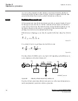
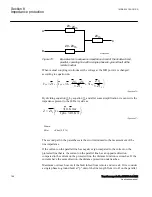
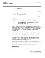
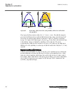
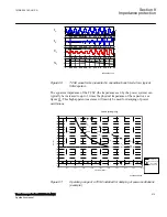
Figure 73:
Equivalent zero sequence impedance circuit of the double-circuit,
parallel, operating line with a single phase-to-ground-fault at the
remote busbar
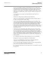
When mutual coupling is introduced, the voltage at the IED point A is changed,
according to equation
0
0
0
0
1
1
3
3
3 1
3 1
m
L
L
ph
p
ph
L
L
L
Z
Z
Z
V
Z
I
I
I
Z
Z
æ
ö
-
=
×
+
×
+
ç
÷
×
×
è
ø
EQUATION1276 V4 EN-US
(Equation 36)
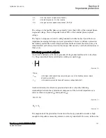
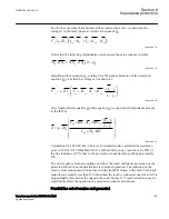
By dividing equation
by equation
and after some simplification we can write the
impedance present to the IED at A side as:
3 0
1 1
3 0
æ
ö
×
=
+
ç
÷
+
×
è
ø
L
I
KNm
Z
Z
I ph
I
KN
EQUATION1277 V3 EN-US
(Equation 37)
Where:
KNm
= Z0m/(3 · Z1L)
The second part in the parentheses is the error introduced to the measurement of the
line impedance.
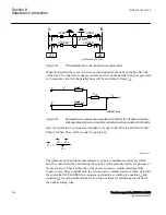
If the current on the parallel line has negative sign compared to the current on the
protected line that is, the current on the parallel line has an opposite direction
compared to the current on the protected line, the distance function overreaches. If the
currents have the same direction, the distance protection underreaches.
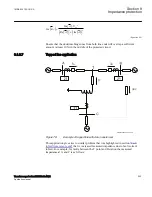
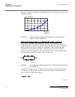
Maximum overreach occurs if the fault infeed from remote end is weak. If we consider
a single phase-to-ground fault at "p" unit of the line length from A to B on the parallel
Section 8
1MRK 504 163-UUS A
Impedance protection
198
Transformer protection RET670 2.2 ANSI
Application manual
Summary of Contents for RELION RET670
Page 1: ...RELION 670 SERIES Transformer protection RET670 Version 2 2 ANSI Application manual ...
Page 2: ......
Page 48: ...42 ...
Page 64: ...58 ...
Page 74: ...68 ...
Page 104: ...98 ...
Page 194: ...188 ...
Page 518: ...512 ...
Page 618: ...612 ...
Page 648: ...642 ...
Page 666: ...660 ...
Page 672: ...666 ...
Page 682: ...676 ...
Page 844: ...838 ...
Page 868: ...862 ...
Page 956: ...950 ...
Page 964: ...958 ...
Page 1004: ...998 ...
Page 1014: ...1008 ...
Page 1015: ...1009 ...


