18.7.2
Application
GUID-F9D225B1-68F7-4D15-AA89-C9211B450D19 v3
The Logical signal status report (BINSTATREP) function makes it possible to poll
signals from various other function blocks.
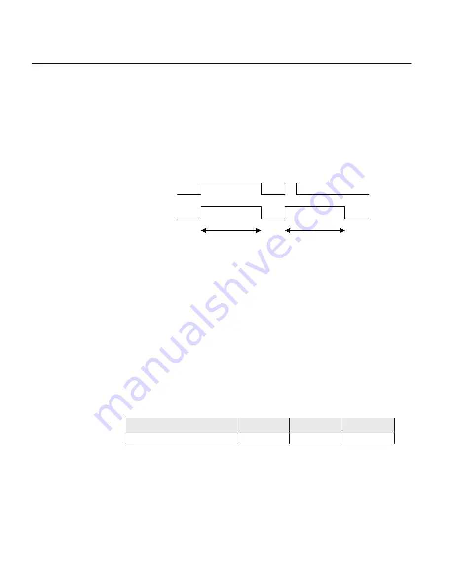
BINSTATREP has 16 inputs and 16 outputs. The output status follows the inputs and
can be read from the local HMI or via SPA communication.
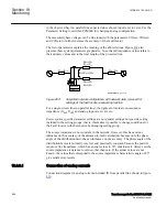
When an input is set, the respective output is set for a user defined time. If the input
signal remains set for a longer period, the output will remain set until the input signal
resets.
t
t
INPUTn
OUTPUTn
IEC09000732-1-en.vsd
IEC09000732 V1 EN-US
Figure 408:
BINSTATREP logical diagram
18.7.3
Setting guidelines
GUID-BBDA6900-4C1A-4A7C-AEA5-3C49C2749254 v2
The pulse time
t
is the only setting for the Logical signal status report (BINSTATREP).
Each output can be set or reset individually, but the pulse time will be the same for all
outputs in the entire BINSTATREP function.
18.8
Fault locator LMBRFLO
IP14592-1 v2
18.8.1
Identification
M14892-1 v3
Function description
IEC 61850
identification
IEC 60617
identification
ANSI/IEEE C37.2
device number
Fault locator
LMBRFLO
-
-
18.8.2
Application
M13752-3 v6
The main objective of line protection and monitoring IEDs is fast, selective and
reliable operation for faults on a protected line section. Besides this, information on
Section 18
1MRK 504 163-UUS A
Monitoring
894
Transformer protection RET670 2.2 ANSI
Application manual
Summary of Contents for RELION RET670
Page 1: ...RELION 670 SERIES Transformer protection RET670 Version 2 2 ANSI Application manual ...
Page 2: ......
Page 48: ...42 ...
Page 64: ...58 ...
Page 74: ...68 ...
Page 104: ...98 ...
Page 194: ...188 ...
Page 518: ...512 ...
Page 618: ...612 ...
Page 648: ...642 ...
Page 666: ...660 ...
Page 672: ...666 ...
Page 682: ...676 ...
Page 844: ...838 ...
Page 868: ...862 ...
Page 956: ...950 ...
Page 964: ...958 ...
Page 1004: ...998 ...
Page 1014: ...1008 ...
Page 1015: ...1009 ...

