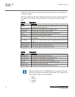
•
SetV
•
VCTRStatus
•
X2
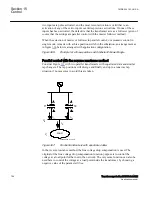
The transformers controlled in parallel with the circulating current method or the
master-follower method must be assigned unique identities. These identities are
entered as a setting in each TR8ATCC (90), and they are predefined as T1, T2, T3,...,
T8 (transformers 1 to 8). In figure
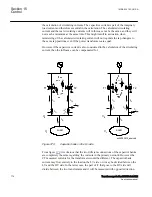
there are three transformers with the parameter
TrfId
set to
T1, T2
and
T3
, respectively.
For parallel control with the circulating current method or the master-follower method
alternatively, the same type of data set as described above, must be exchanged between
two TR8ATCC (90). To achieve this, each TR8ATCC (90) is transmitting its own data
set on the output ATCCOUT as previously mentioned. To receive data from the other
transformers in the parallel group, the output ATCCOUT from each transformer must
be connected (via GOOSE or internally in the application configuration) to the inputs
HORIZx (x = identifier for the other transformers in the parallel group) on TR8ATCC
(90) function block. Apart from this, there is also a setting in each TR8ATCC =/,..., =/
T1RXOP=Off/On,..., T8RXOP=Off/ On
. This setting determines from which of the
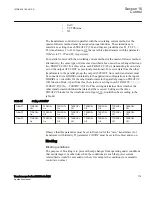
other transformer individuals that data shall be received. Settings in the three
TR8ATCC blocks for the transformers in figure
, would then be according to the
table
:
Table 59:
Setting of TxRXOP
TrfId=T1
T1RXOP=
Off
T2RXOP=
On
T3RXOP=
On
T4RXOP=
Off
T5RXOP=
Off
T6RXOP=
Off
T7RXOP=
Off
T8RXOP=
Off
TrfId=T2
T1RXOP=
On
T2RXOP=
Off
T3RXOP=
On
T4RXOP=
Off
T5RXOP=
Off
T6RXOP=
Off
T7RXOP=
Off
T8RXOP=
Off
TrfId=T3
T1RXOP=
On
T2RXOP=
On
T3RXOP=
Off
T4RXOP=
Off
T5RXOP=
Off
T6RXOP=
Off
T7RXOP=
Off
T8RXOP=
Off
Observe that this parameter must be set to
Disabled
for the “own” transformer. (for
transformer with identity T1 parameter
T1RXOP
must be set to
Disabled
, and so on.
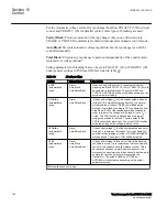
Blocking
SEMOD159053-275 v2
Blocking conditions
SEMOD159053-277 v6
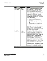
The purpose of blocking is to prevent the tap changer from operating under conditions
that can damage it, or otherwise when the conditions are such that power system
related limits would be exceeded or when, for example the conditions for automatic
control are not met.
1MRK 504 163-UUS A
Section 15
Control
Transformer protection RET670 2.2 ANSI
779
Application manual
Summary of Contents for RELION RET670
Page 1: ...RELION 670 SERIES Transformer protection RET670 Version 2 2 ANSI Application manual ...
Page 2: ......
Page 48: ...42 ...
Page 64: ...58 ...
Page 74: ...68 ...
Page 104: ...98 ...
Page 194: ...188 ...
Page 518: ...512 ...
Page 618: ...612 ...
Page 648: ...642 ...
Page 666: ...660 ...
Page 672: ...666 ...
Page 682: ...676 ...
Page 844: ...838 ...
Page 868: ...862 ...
Page 956: ...950 ...
Page 964: ...958 ...
Page 1004: ...998 ...
Page 1014: ...1008 ...
Page 1015: ...1009 ...

