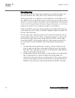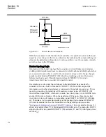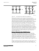
ATCC
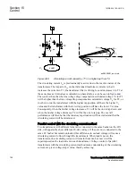
IED
HV-side
Pforward
LV-side
ANSI06000536-2-en.vsd
Qforward
(inductive)
ANSI06000536 V2 EN-US
Figure 371:
Power direction references
With the four outputs in the function block available, it is possible to do more than just
supervise a level of power flow in one direction. By combining the outputs with logical
elements in application configuration, it is also possible to cover for example, intervals
as well as areas in the P-Q plane.
Busbar topology logic
SEMOD159053-259 v3
Information of the busbar topology that is, position of circuit breakers and isolators,
yielding which transformers that are connected to which busbar and which busbars that
are connected to each other, is vital for the Automatic voltage control for tap changer,
parallel control function TR8ATCC (90) when the circulating current or the master-
follower method is used. This information tells each TR8ATCC (90), which
transformers that it has to consider in the parallel control.
In a simple case, when only the switchgear in the transformer bays needs to be
considered, there is a built-in function in TR8ATCC (90) block that can provide
information on whether a transformer is connected to the parallel group or not. This is
made by connecting the transformer CB auxiliary contact status to TR8ATCC (90)
function block input DISC, which can be made via a binary input, or via GOOSE from
another IED in the substation. When the transformer CB is open, this activates that
input which in turn will make a corresponding signal DISC=1 in TR8ATCC (90) data
set. This data set is the same data package as the package that contains all TR8ATCC
(90) data transmitted to the other transformers in the parallel group (see section
"Exchange of information between TR8ATCC functions"
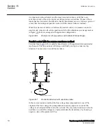
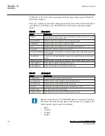
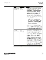
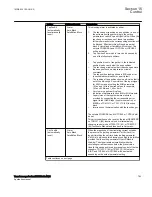
shows an example where T3 is disconnected which will lead to T3 sending the DISC=1
signal to the other two parallel TR8ATCC (90) modules (T1 and T2) in the group. Also
see table
.
Section 15
1MRK 504 163-UUS A
Control
776
Transformer protection RET670 2.2 ANSI
Application manual
Summary of Contents for RELION RET670
Page 1: ...RELION 670 SERIES Transformer protection RET670 Version 2 2 ANSI Application manual ...
Page 2: ......
Page 48: ...42 ...
Page 64: ...58 ...
Page 74: ...68 ...
Page 104: ...98 ...
Page 194: ...188 ...
Page 518: ...512 ...
Page 618: ...612 ...
Page 648: ...642 ...
Page 666: ...660 ...
Page 672: ...666 ...
Page 682: ...676 ...
Page 844: ...838 ...
Page 868: ...862 ...
Page 956: ...950 ...
Page 964: ...958 ...
Page 1004: ...998 ...
Page 1014: ...1008 ...
Page 1015: ...1009 ...

