


L1
(A)
L2
(B)
L3
(C)
Protected Object
CT 1500/5
Star/Wye
Connected
7
8
9
10
11
12
1
2
3
4
5
6
AI01 (I)
AI02 (I)
AI03 (I)
AI04 (I)
AI05 (I)
AI06 (I)
6
IED
X1
R
1
1
2
4
5
V
R
2
1
3
4
2
1
2
3
N
1-Ph Plate with Metrosil and Resistor
2
3
5
4
N
L1
(A)
L2
(B)
L3
(C)
C
T
1
5
0
0
/5
1
ANSI09000170-5-en.vsdx
SMAI2
BLOCK
REVROT
^GRP2_A
^GRP2_B
^GRP2_C
^GRP2_N
G2AI3P
G2AI1
G2AI2
G2AI3
G2AI4
G2N
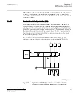
ANSI09000170 V5 EN-US
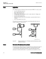
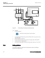
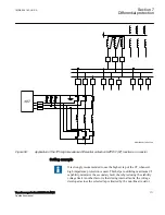
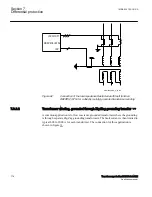
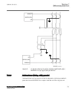
Figure 57:
CT connections for restricted earth fault protection
Pos
Description
1
Scheme grounding point
Ensure that only one grounding point exists in this scheme.
2
One-phase plate with stabilizing resistor and metrosil. Protective ground is a separate 4 mm screw
terminal on the plate.
3
Necessary connection for the metrosil.
4
Position of optional test switch for secondary injection into the high impedance differential IED.
5
Necessary connection for stabilizing resistor.
6
How to connect the high impedance restricted earth fault protection scheme to one CT input in IED.
7.2.4
Setting guidelines
IP14945-1 v1
M13076-3 v2
The setting calculations are individual for each application. Refer to the different
application descriptions below.
Section 7
1MRK 504 163-UUS A
Differential protection
166
Transformer protection RET670 2.2 ANSI
Application manual
Summary of Contents for RELION RET670
Page 1: ...RELION 670 SERIES Transformer protection RET670 Version 2 2 ANSI Application manual ...
Page 2: ......
Page 48: ...42 ...
Page 64: ...58 ...
Page 74: ...68 ...
Page 104: ...98 ...
Page 194: ...188 ...
Page 518: ...512 ...
Page 618: ...612 ...
Page 648: ...642 ...
Page 666: ...660 ...
Page 672: ...666 ...
Page 682: ...676 ...
Page 844: ...838 ...
Page 868: ...862 ...
Page 956: ...950 ...
Page 964: ...958 ...
Page 1004: ...998 ...
Page 1014: ...1008 ...
Page 1015: ...1009 ...


