compensated and adjacent lines are concentrated on finding some parallel ways, which
may help eliminating the basic reason for wrong measurement. The most known of
them are decrease of the reach due to presence of series capacitor, which apparently
decreases the line reactance, and introduction of permanent memory voltage in
directional measurement.
Series compensated and adjacent lines are often the more important links in a
transmission networks and delayed fault clearance is undesirable. This makes it
necessary to install distance protection in combination with telecommunication. The
most common is distance protection in Permissive Overreaching Transfer Trip mode
(POTT).
8.13.3.6
Underreaching and overreaching schemes
GUID-3090702F-508B-480C-9AC7-2D5A82B9AD1E v1
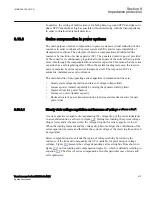
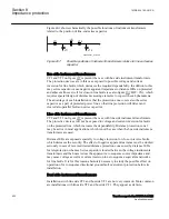
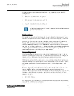
It is a basic rule that the underreaching distance protection zone should under no
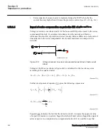
circumstances overreach for the fault at the remote end bus, and the overreaching zone
should always, under all system conditions, cover the same fault. In order to obtain
section selectivity, the first distance (underreaching) protection zone must be set to a
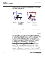
reach less than the reactance of the compensated line in accordance with figure
.
en06000618.vsd
X
11
X
12
-
j X
C
A
B
D
A
D
B
Zone 1
A
Zone 1
B
Zone 2
A
Zone 2
B
G
IEC06000618 V1 EN-US
Figure 213:
Underreaching (Zone 1) and overreaching (Zone 2) on series
compensated line
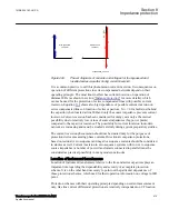
The underreaching zone will have reduced reach in cases of bypassed series capacitor,
as shown in the dashed line in figure
. The overreaching zone (Zone 2) can this way
cover bigger portion of the protected line, but must always cover with certain margin
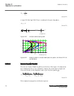
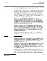
the remote end bus. Distance protection Zone 1 is often set to
(
)
1
11
12
=
×
+
-
Z
S
C
X
K
X
X
X
EQUATION1914 V1 EN-US
(Equation 339)
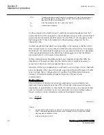
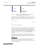
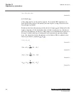
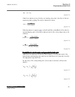
Here K
S
is a safety factor, presented graphically in figure
, which covers for
possible overreaching due to low frequency (sub-harmonic) oscillations. Here it should
be noted separately that compensation degree K
C
reactance, inclusive line and source impedance reactance. The same setting applies
regardless MOV or spark gaps are used for capacitor overvoltage protection.
Section 8
1MRK 504 163-UUS A
Impedance protection
426
Transformer protection RET670 2.2 ANSI
Application manual
Summary of Contents for RELION RET670
Page 1: ...RELION 670 SERIES Transformer protection RET670 Version 2 2 ANSI Application manual ...
Page 2: ......
Page 48: ...42 ...
Page 64: ...58 ...
Page 74: ...68 ...
Page 104: ...98 ...
Page 194: ...188 ...
Page 518: ...512 ...
Page 618: ...612 ...
Page 648: ...642 ...
Page 666: ...660 ...
Page 672: ...666 ...
Page 682: ...676 ...
Page 844: ...838 ...
Page 868: ...862 ...
Page 956: ...950 ...
Page 964: ...958 ...
Page 1004: ...998 ...
Page 1014: ...1008 ...
Page 1015: ...1009 ...

