


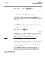


Both current limits
IMinOpPGZx
and
IMinOpPPZx
are automatically reduced to 75%
of regular set values if the zone is set to operate in reverse direction, that is,
OperationDir
is set to
Reverse
.
OpModePPZx
and
OpModePEZx
These settings, two per zone (x=1,2..5&RV), with options {Off, Quadrilateral, Mho,
Offset}, are used to set the operation and characteristic for phase-to-earth and phase-to-
phase faults, respectively.
For example, in one zone it is possible to choose Mho characteristic for the three Ph-Ph
measuring loops and Quadrilateral characteristic for the three Ph-E measuring loops.
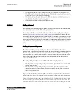
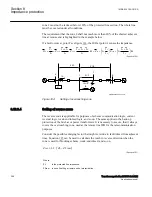
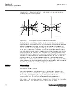
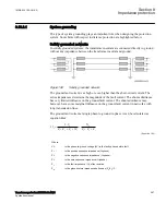
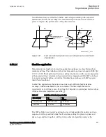
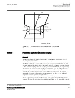
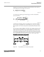
DirModeZx
This setting defines the operating direction for zones Z3, Z4 and Z5 (the directionality
of zones Z1, Z2 and ZRV is fixed). The options are
Non-directional
,
Forward
or
Reverse
. The result from respective set value is illustrated in figure
, where the
positive impedance corresponds to the direction out on the protected line.
IEC05000182-2-en.vsdx
R
X
R
X
R
X
Non-directional
Forward
Reverse
IEC05000182 V2 EN-US
Figure 186:
Directional operating modes of the distance measuring zones 3 to 5
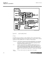
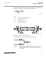
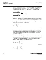
tPPZx
,
tPGZx
,
TimerModeZx
,
ZoneLinkPU
and
TimerLinksZx
The logic for the linking of the timer settings can be described with a module diagram.
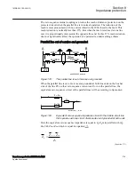
The following figure shows only the case when
TimerModeZx
is selected to
Ph-Ph
and
Ph-G
.
1MRK 504 163-UUS A
Section 8
Impedance protection
Transformer protection RET670 2.2 ANSI
393
Application manual
Summary of Contents for RELION RET670
Page 1: ...RELION 670 SERIES Transformer protection RET670 Version 2 2 ANSI Application manual ...
Page 2: ......
Page 48: ...42 ...
Page 64: ...58 ...
Page 74: ...68 ...
Page 104: ...98 ...
Page 194: ...188 ...
Page 518: ...512 ...
Page 618: ...612 ...
Page 648: ...642 ...
Page 666: ...660 ...
Page 672: ...666 ...
Page 682: ...676 ...
Page 844: ...838 ...
Page 868: ...862 ...
Page 956: ...950 ...
Page 964: ...958 ...
Page 1004: ...998 ...
Page 1014: ...1008 ...
Page 1015: ...1009 ...


