


•
Errors introduced by current and voltage instrument transformers, particularly
under transient conditions.
•
Inaccuracies in the line zero sequence impedance data, and their effect on the
calculated value of the ground-return compensation factor.
•
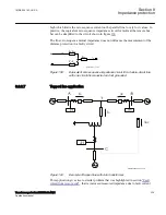
The effect of infeed between the IED and the fault location, including the
influence of different Z
0
/Z
1
ratios of the various sources.
•
The phase impedance of non transposed lines is not identical for all fault loops.
The difference between the impedances for different phase-to-ground loops can be
as large as 5-10% of the total line impedance.
•
The effect from load transfer together with fault resistance may be considerable in
some extreme cases.
•
Zero sequence mutual coupling from parallel lines.
8.9.3.2
Setting of zone 1
GUID-36A888E8-F209-478E-B8C4-76370B644386 v1
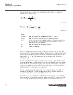
The different errors mentioned earlier usually require a limitation of the underreaching
zone (normally zone 1) to 75 - 90% of the protected line.
In case of parallel lines, consider the influence of the mutual coupling according to
section
"Parallel line application with mutual coupling"
and select the case(s) that are
valid in the particular application. By proper setting it is possible to compensate for the
cases when the parallel line is in operation, out of service and not grounded and out of
service and grounded in both ends. The setting of ground-fault reach should be selected
to be <95% also when parallel line is out of service and grounded at both ends (worst
case).
8.9.3.3
Setting of overreaching zone
GUID-2C36623A-7A29-4881-9F33-DA5F5FD36DE5 v1
The first overreaching zone (normally zone 2) must detect faults on the whole
protected line. Considering the different errors that might influence the measurement in
the same way as for zone 1, it is necessary to increase the reach of the overreaching
zone to at least 120% of the protected line. The zone 2 reach can be even longer if the
fault infeed from adjacent lines at remote end are considerable higher than the fault
current at the IED location.
The setting shall generally not exceed 80% of the following impedances:
•
The impedance corresponding to the protected line, plus the first zone reach of the
shortest adjacent line.
•
The impedance corresponding to the protected line, plus the impedance of the
maximum number of transformers operating in parallel on the bus at the remote
end of the protected line.
Section 8
1MRK 504 163-UUS A
Impedance protection
338
Transformer protection RET670 2.2 ANSI
Application manual
Summary of Contents for RELION RET670
Page 1: ...RELION 670 SERIES Transformer protection RET670 Version 2 2 ANSI Application manual ...
Page 2: ......
Page 48: ...42 ...
Page 64: ...58 ...
Page 74: ...68 ...
Page 104: ...98 ...
Page 194: ...188 ...
Page 518: ...512 ...
Page 618: ...612 ...
Page 648: ...642 ...
Page 666: ...660 ...
Page 672: ...666 ...
Page 682: ...676 ...
Page 844: ...838 ...
Page 868: ...862 ...
Page 956: ...950 ...
Page 964: ...958 ...
Page 1004: ...998 ...
Page 1014: ...1008 ...
Page 1015: ...1009 ...


