


time delay (inverse or definite time) is set to avoid unnecessary operation during
shorter voltage deviations from the target value, and in order to coordinate with other
automatic voltage controllers in the system.
TCMYLTC and TCLYLTC (84)are an interface between the Automatic voltage control
for tap changer, TR1ATCC (90) or TR8ATCC (90) and the transformer load tap
changer itself. More specifically this means that it gives command-pulses to a power
transformer motor driven load tap changer and that it receives information from the
load tap changer regarding tap position, progress of given commands, and so on.
TCMYLTC and TCLYLTC (84) also serve the purpose of giving information about tap
position to the transformer differential protection.
Control location local/remote
SEMOD159053-30 v3
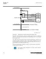
The tap changer can be operated from the front of the IED or from a remote place
alternatively. On the IED front there is a local remote switch that can be used to select
the operator place. For this functionality the Apparatus control function blocks Bay
control (QCBAY), Local remote (LOCREM) and Local remote control
(LOCREMCTRL) are used.
Information about the control location is given to TR1ATCC (90) or TR8ATCC (90)
function through connection of the Permitted Source to Operate (PSTO) output of the
QCBAY function block to the input PSTO of the TR1ATCC (90) or TR8ATCC (90)
function block.
Control Mode
SEMOD159053-35 v4
The control mode of the automatic voltage control for tap changer function, TR1ATCC
(90) for single control and TR8ATCC (90) for parallel control can be:
•
Manual
•
Automatic
The control mode can be changed from the local location via the command menu on
the local HMI under
Main menu/Control/Commands/
TransformerVoltageControl(ATCC,90)/TR1ATCC:x/TR8ATCC:x
, or changed
from a remote location via binary signals connected to the MANCTRL, AUTOCTRL
inputs on TR1ATCC (90) or TR8ATCC (90) function block.
Measured Quantities
SEMOD159053-61 v4
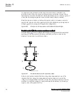
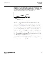
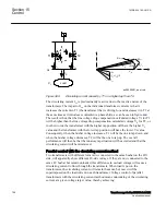
In normal applications, the LV side of the transformer is used as the voltage measuring
point. If necessary, the LV side current is used as load current to calculate the line-
voltage drop to the regulation point.
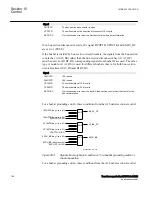
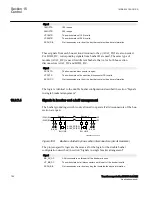
Automatic voltage control for tap changer, TR1ATCC (90) for single control and
TR8ATCC (90) for parallel control function block has three inputs I3P1, I3P2 and
V3P2 corresponding to HV-current, LV-current and LV-voltage respectively. These
Section 15
1MRK 504 163-UUS A
Control
756
Transformer protection RET670 2.2 ANSI
Application manual
Summary of Contents for RELION RET670
Page 1: ...RELION 670 SERIES Transformer protection RET670 Version 2 2 ANSI Application manual ...
Page 2: ......
Page 48: ...42 ...
Page 64: ...58 ...
Page 74: ...68 ...
Page 104: ...98 ...
Page 194: ...188 ...
Page 518: ...512 ...
Page 618: ...612 ...
Page 648: ...642 ...
Page 666: ...660 ...
Page 672: ...666 ...
Page 682: ...676 ...
Page 844: ...838 ...
Page 868: ...862 ...
Page 956: ...950 ...
Page 964: ...958 ...
Page 1004: ...998 ...
Page 1014: ...1008 ...
Page 1015: ...1009 ...


