


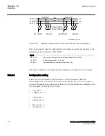

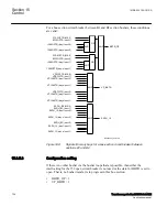


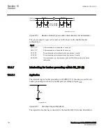

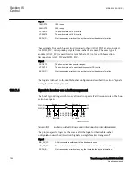
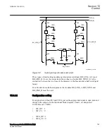

The same type of module (A1A2_DC) is used for different busbars, that is, for both
bus-section disconnector A1A2_DC and B1B2_DC. But for B1B2_DC, corresponding
signals from busbar B are used.
en04000498_ansi.vsd
Section 1
Section 2
A1A2_DC(BS)
B1B2_DC(BS)
DB_BUS DB_BUS
DB_BUS DB_BUS
(WA1)A1
(WA2)B1
B2
A2
ANSI04000498 V1 EN-US
Figure 345:
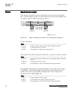
Busbars divided by bus-section disconnectors (circuit breakers)
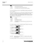
To derive the signals:
Signal
S1DC_OP
All disconnectors on bus-section 1 are open.
S2DC_OP
All disconnectors on bus-section 2 are open.
VPS1_DC
The switch status of all disconnectors on bus-section 1 is valid.
VPS2_DC
The switch status of all disconnectors on bus-section 2 is valid.
EXDU_BB
No transmission error from double-breaker bay (DB) that contains the above
information.
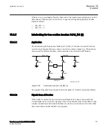
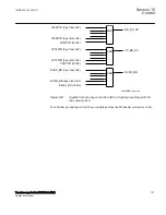
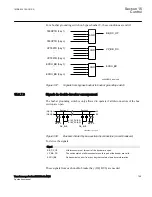
These signals from each double-breaker bay (DB_BUS) are needed:
Signal
189OPTR
189 is open.
289OPTR
289 is open.
VP189TR
The switch status of 189 is valid.
VP289TR
The switch status of 289 is valid.
EXDU_DB
No transmission error from the bay that contains the above information.
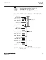
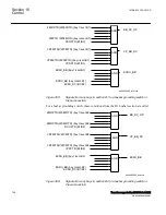
The logic is identical to the double busbar configuration “Signals in single breaker
arrangement”.
For a bus-section disconnector, these conditions from the A1 busbar section are valid:
1MRK 504 163-UUS A
Section 15
Control
Transformer protection RET670 2.2 ANSI
741
Application manual
Summary of Contents for RELION RET670
Page 1: ...RELION 670 SERIES Transformer protection RET670 Version 2 2 ANSI Application manual ...
Page 2: ......
Page 48: ...42 ...
Page 64: ...58 ...
Page 74: ...68 ...
Page 104: ...98 ...
Page 194: ...188 ...
Page 518: ...512 ...
Page 618: ...612 ...
Page 648: ...642 ...
Page 666: ...660 ...
Page 672: ...666 ...
Page 682: ...676 ...
Page 844: ...838 ...
Page 868: ...862 ...
Page 956: ...950 ...
Page 964: ...958 ...
Page 1004: ...998 ...
Page 1014: ...1008 ...
Page 1015: ...1009 ...


