


8.1.3.2
Setting of zone1
SEMOD168247-15 v2
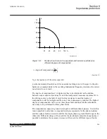
The different errors mentioned earlier usually require a limitation of the underreaching
zone (normally zone 1) to 75 - 90% of the protected line.
In case of parallel lines, consider the influence of the mutual coupling according to
section
"Parallel line application with mutual coupling"
and select the case(s) that are
valid in your application. We recommend to compensate setting for the cases when the
parallel line is in operation, out of service and not grounded and out of service and
grounded in both ends. The setting of ground fault reach should be selected to be <85%
also when parallel line is out of service and grounded at both ends (worst case).
8.1.3.3
Setting of overreaching zone
SEMOD168247-19 v2
The first overreaching zone (normally zone2) must detect faults on the whole protected
line. Considering the different errors that might influence the measurement in the same
way as for zone1, it is necessary to increase the reach of the overreaching zone to at
least 120% of the protected line. The zone2 reach can be even higher if the fault infeed
from adjacent lines at remote end are considerable higher than the fault current at the
IED location.
The setting must not exceed 80% of the following impedances:
•
The impedance corresponding to the protected line, plus the first zone reach of the
shortest adjacent line.
•
The impedance corresponding to the protected line, plus the impedance of the
maximum number of transformers operating in parallel on the bus at the remote
end of the protected line.
If the requirements in the bullet—listed paragraphs above gives a zone2 reach less than
120%, the time delay of zone2 must be increased by approximately 200ms to avoid
unwanted operation in cases when the telecommunication for the short adjacent line at
remote end is down during faults. The zone2 must not be reduced below 120% of the
protected line section. The whole line must be covered under all conditions.
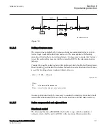
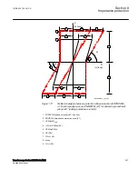
The requirement that the zone 2 shall not reach more than 80% of the shortest adjacent
line at remote end is highlighted with a simple example below.
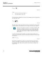
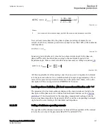
If a fault occurs at point F (as shown in figure
, also for the explanation of all
abbreviations used), the IED at point A senses the impedance:
Z
V
I
Z
I
I
I
Z
I
I
I
I
R
Z
I
I
Z
AF
A
A
AC
A
C
A
CF
A
C
B
A
F
AC
C
A
C
=
=
+
+
⋅
+
+
+
⋅
=
+
+
⋅
1
F
F
C
B
A
F
I
I
I
R
+
+
+
⋅
1
EQUATION302 V5 EN-US
(Equation 81)
Section 8
1MRK 504 163-UUS A
Impedance protection
236
Transformer protection RET670 2.2 ANSI
Application manual
Summary of Contents for RELION RET670
Page 1: ...RELION 670 SERIES Transformer protection RET670 Version 2 2 ANSI Application manual ...
Page 2: ......
Page 48: ...42 ...
Page 64: ...58 ...
Page 74: ...68 ...
Page 104: ...98 ...
Page 194: ...188 ...
Page 518: ...512 ...
Page 618: ...612 ...
Page 648: ...642 ...
Page 666: ...660 ...
Page 672: ...666 ...
Page 682: ...676 ...
Page 844: ...838 ...
Page 868: ...862 ...
Page 956: ...950 ...
Page 964: ...958 ...
Page 1004: ...998 ...
Page 1014: ...1008 ...
Page 1015: ...1009 ...


