


•
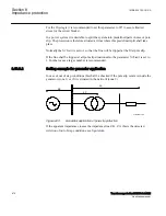
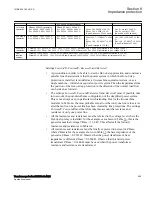
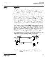
For the synchronous machines as the generator in Table
Xd' shall be used. This due to the relatively slow electromechanical oscillations
under out-of-step conditions.
•
Sometimes the equivalent resistance of the generator is difficult to get. A good
estimate is 1 percent of transient reactance Xd'. No great error is done if this
resistance is set to zero (0).
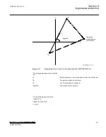
•
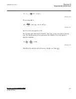
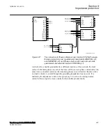
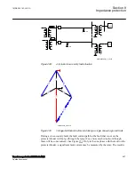
Inclination of the Z-line, connecting points SE and RE, against the real (R) axis
can be calculated as arctan ((
ReverseX
+
ForwardX
) / (
ReverseR
+
ForwardR
)),
and is for the case in Table
equal to 84.55 degrees, which is a typical value.
Other settings:
•
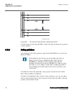
ReachZ1
: Determines the reach of the zone 1 in the forward direction. Determines
the position of the X-line which delimits zone 1 from zone 2. Set in % of
ForwardX
. In the case shown in Table
, where the reactance of the step-up
power transformer is 11.32 % of the total
ForwardX
, the setting
ReachZ1
should
be set to
ReachZ1
=
12
%. This means that the generator – step-up transformer
unit would be in the zone 1. In other words, if the centre of oscillation would be
found to be within the zone 1, only a very limited number of pole-slips would be
allowed, usually only one.
•
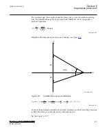
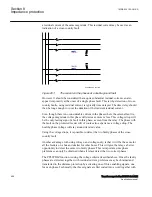
pick up Angle
: Angle between the two equivalent rotors induced voltages (that is,
the angle between the two internal induced voltages E1 and E2 in an equivalent
simplified two-machine system) to get the pickup signal, in degrees. The width of
the lens characteristic is determined by the value of this setting. Whenever the
complex impedance Z(R, X) enters the lens, this is a sign of instability. The angle
recommended is 110 or 120 degrees, because it is at this rotor angle where
problems with dynamic stability usually begin. Power angle 120 degrees is
sometimes called “the angle of no return” because if this angle is reached under
generator swings, the generator is most likely to lose synchronism. When the
complex impedance Z(R, X) enters the lens the start output signal (
PICKUP
) is set
to 1 (
TRUE
).
•
TripAngle
: The setting
TripAngle
specifies the value of the rotor angle where the
trip command is sent to the circuit breaker in order to minimize the stress to which
the breaker is exposed when breaking the currents. The range of this value is from
15° to 90°, with higher values suitable for longer breaker opening times. If a
breaker opening is initiated at for example 60°, then the circuit breaker opens its
contacts closer to 0°, where the currents are smaller. If the breaker opening time
tBreaker
is known, then it is possible to calculate more exactly when opening must
be initiated in order to open the circuit breaker contacts as close as possible to 0°,
where the currents are smallest. If the breaker opening time
tBreaker
is specified
(that is, higher than the default 0.0 s, where 0.0 s means that
tBreaker
is unknown),
then this alternative way to determine the moment when a command to open the
breaker is sent, is automatically chosen instead of the more approximate method,
based on the
TripAngle
.
Section 8
1MRK 504 163-UUS A
Impedance protection
486
Transformer protection RET670 2.2 ANSI
Application manual
Summary of Contents for RELION RET670
Page 1: ...RELION 670 SERIES Transformer protection RET670 Version 2 2 ANSI Application manual ...
Page 2: ......
Page 48: ...42 ...
Page 64: ...58 ...
Page 74: ...68 ...
Page 104: ...98 ...
Page 194: ...188 ...
Page 518: ...512 ...
Page 618: ...612 ...
Page 648: ...642 ...
Page 666: ...660 ...
Page 672: ...666 ...
Page 682: ...676 ...
Page 844: ...838 ...
Page 868: ...862 ...
Page 956: ...950 ...
Page 964: ...958 ...
Page 1004: ...998 ...
Page 1014: ...1008 ...
Page 1015: ...1009 ...


