


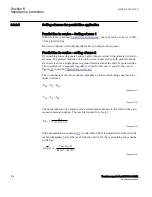


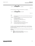


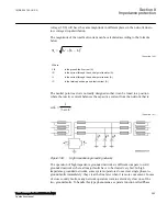


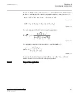

Calculate the step-up transformer impedance, in primary ohms, from the 13kV side as
follows:
2
2
10 13
0, 26
100
100 65
t
r
T
x
U
X
S
=
×
=
×
=
W
IEC-EQUATION2318 V1 EN-US
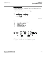
Then the reach in primary ohms shall be set to 100% of transformer impedance. Thus
the reach shall be set to 0,26Ω primary.
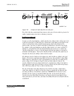
Set the first zone of Full-scheme distance measuring, Mho characteristic ZMHPDIS
(21) to disable phase-to-ground loops and enable phase-to-phase loops:
•
The parameter
GlobalBaseSel
shall be set in order to select the global base value
group GBASVAL where the base voltage
UBaseVBase
and the base current
IBase
are defined;
UBaseVBase
is the generator rated phase-phase voltage
(
VBase
=13,2kV) and
IBase
is the generator rated phase current (
IBase
=3062A).
•
Parameter
DirMode
shall be set to
Offset.
•
Parameter
OffsetMhoDir
shall be set to
Non-directional.
•
The phase-to-ground measuring loops shall be disabled by setting
OpModePG
=
Disabled
•
The phase-to-phase measuring loops shall be enabled and corresponding settings
in primary ohms for forward and reserve reach and time delay shall be entered
accordingly:
•
Parameter
ZPP
shall be set to
0,260Ω.
•
Parameter
ZrevPP
shall be set to
0,260Ω.
•
Parameter
tPP
shall be set to
1,0000s.
•
Parameter
ZAngPP
shall be set to default value
85 Deg
.
Set the following for the directional element ZDMRDIR:
•
The parameter
GlobalBaseSel
shall be set in order to select the global base value
group GBASVAL where the base voltage
UBaseVBase
and the base current
IBase
are defined;
UBaseVBase
is the generator rated phase-phase voltage
(
VBase
=13,2kV) and
IBase
is the generator rated phase current (
IBase
=3062A).
•
Parameter
DirEvalType
shall be set to
Imp/Comp
.
•
Other settings can be left on the default values.
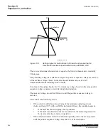
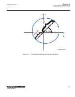
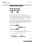
By doing this offset mho characteristic for zone one will be achieved as shown in
figure
. Note that for this particular example
ZPP
=
ZRevPP
=
0,26Ω
. Thus the
operating characteristic for this particular application will be a circle with a centre in
the impedance plane origo.
By following the same procedure other mho zones can be set.
Section 8
1MRK 504 163-UUS A
Impedance protection
288
Transformer protection RET670 2.2 ANSI
Application manual
Summary of Contents for RELION RET670
Page 1: ...RELION 670 SERIES Transformer protection RET670 Version 2 2 ANSI Application manual ...
Page 2: ......
Page 48: ...42 ...
Page 64: ...58 ...
Page 74: ...68 ...
Page 104: ...98 ...
Page 194: ...188 ...
Page 518: ...512 ...
Page 618: ...612 ...
Page 648: ...642 ...
Page 666: ...660 ...
Page 672: ...666 ...
Page 682: ...676 ...
Page 844: ...838 ...
Page 868: ...862 ...
Page 956: ...950 ...
Page 964: ...958 ...
Page 1004: ...998 ...
Page 1014: ...1008 ...
Page 1015: ...1009 ...


