tZ2
: Zone 2 trip time delay in seconds. Time delay should be provided in order to
coordinate with zone 1 element provided for the outgoing line.
Zone 3
Zone 3 in ZGVPDIS function has offset mho characteristic and it can evaluate three
phase-to-phase impedance measuring loops or
EnhancedReach
loop
OpModeZ3
: Zone 3 distance element can be selected as
Disabled
,
PP Loops
or
EnhancedReach
. It is recommended to select
EnhancedReach
setting.
Z3Fwd
: Zone 3 forward reach in percentage. It is recommended to set zone 3 forward
reach to coordinate with the longest time delay for the transmission line protection
connected to the generating substation bus. Alternatively it can be set to 80% of the
load impedance considering maximum short time over load of the generator.
Z3Rev
: Zone 3 reverse reach in percentage. It is recommended to give limited reverse
reach to ensure operation for close in faults and to minimize area covered in R-X plane.
A setting of 8%. is recommended.
tZ3
: Zone 3 operates time delay in seconds. Time delay is provided in order to
coordinate with slowest circuit backup protection or slowest local backup for faults
within zone 3 reach. A safety margin of 100 ms should be considered.
8.21.3.2
Load encroachment
GUID-EF64E2B4-2B84-421A-B719-2DCA6883D21A v2
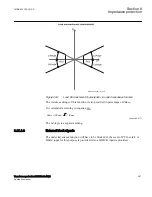
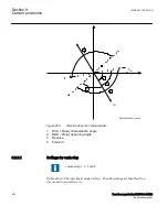
The settings involved in load encroachment feature are:
LdAngle
: Angle in degrees of load encroachment characteristics
RLd
: Positive sequence resistance in per unit
The procedure of calculating the settings for load encroachment consists basically of
defining load angle
LdAngle
and resistive blinder
RLd
. The load encroachment logic
can be enabled for zone 2 and zone 3 elements. For zone 2, the load encroachment can
be enabled or disabled using the
LoadEnchModZ2
setting by selecting either
Enabled
or
Disabled
. Similarly for zone 3 load encroachment can be enabled or disabled using
the
LoadEnchModZ3
setting by selecting either
Enabled
or
Disabled
.
The load angle
LdAngle
is same in forward and reverse direction, so it is suitable to
begin the calculation of the parameter setting. The parameter is set to the maximum
possible load angle at the maximum active load. A value larger than 20° must be used.
The blinder
RLd
can be calculated according to the equation
1MRK 504 163-UUS A
Section 8
Impedance protection
Transformer protection RET670 2.2 ANSI
509
Application manual
Summary of Contents for RELION RET670
Page 1: ...RELION 670 SERIES Transformer protection RET670 Version 2 2 ANSI Application manual ...
Page 2: ......
Page 48: ...42 ...
Page 64: ...58 ...
Page 74: ...68 ...
Page 104: ...98 ...
Page 194: ...188 ...
Page 518: ...512 ...
Page 618: ...612 ...
Page 648: ...642 ...
Page 666: ...660 ...
Page 672: ...666 ...
Page 682: ...676 ...
Page 844: ...838 ...
Page 868: ...862 ...
Page 956: ...950 ...
Page 964: ...958 ...
Page 1004: ...998 ...
Page 1014: ...1008 ...
Page 1015: ...1009 ...

