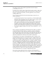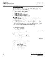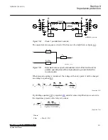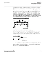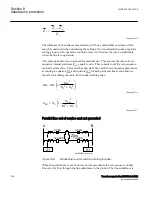
This type of network is many times operated in radial, but can also be found operating
meshed networks.
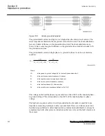
What is typical for this type of network is that the magnitude of the ground fault
current is very low compared to the short circuit current. The voltage on the healthy
phases will get a magnitude of √3 times the phase voltage during the fault. The zero
sequence voltage (3V
0
) will have the same magnitude in different places in the network
due to low voltage drop distribution.
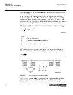
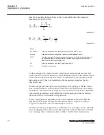
The magnitude of the total fault current can be calculated according to equation
.
(
)
2
2
R
L
C
0
3I
I
I
I
=
+
-
EQUATION1271 V3 EN-US
(Equation 204)
Where:
3I
0
is the ground-fault current (A)
I
R
is the current through the neutral point resistor (A)
I
L
is the current through the neutral point reactor (A)
I
C
is the total capacitive ground-fault current (A)
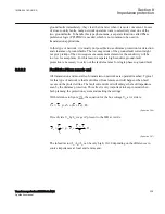
The neutral point reactor is normally designed so that it can be tuned to a position
where the reactive current balances the capacitive current from the network that is:
1
3
L
C
w
w
=
× ×
EQUATION1272 V1 EN-US
(Equation 205)
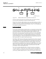
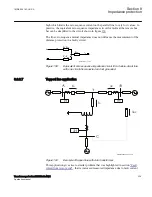
ANSI05000216 V2 EN-US
Figure 151:
High impedance grounded network.
The operation of high impedance grounded networks is different compared to solid
grounded networks where all major faults have to be cleared very fast. In high
impedance grounded networks, some system operators do not clear single phase-to-
Section 8
1MRK 504 163-UUS A
Impedance protection
324
Transformer protection RET670 2.2 ANSI
Application manual
Summary of Contents for RELION RET670
Page 1: ...RELION 670 SERIES Transformer protection RET670 Version 2 2 ANSI Application manual ...
Page 2: ......
Page 48: ...42 ...
Page 64: ...58 ...
Page 74: ...68 ...
Page 104: ...98 ...
Page 194: ...188 ...
Page 518: ...512 ...
Page 618: ...612 ...
Page 648: ...642 ...
Page 666: ...660 ...
Page 672: ...666 ...
Page 682: ...676 ...
Page 844: ...838 ...
Page 868: ...862 ...
Page 956: ...950 ...
Page 964: ...958 ...
Page 1004: ...998 ...
Page 1014: ...1008 ...
Page 1015: ...1009 ...

