Arcteq AQ-101DLV, Manual
The Arcteq AQ-101DLV user manual is available for free download on our website. This comprehensive manual provides detailed instructions and information on operating and maintaining the AQ-101DLV. Get the most out of your product with this essential manual, exclusively at manualshive.com.
Share
Download


Reviews:
No comments
Related manuals for AQ-101DLV

PCM2
Brand: OBR Pages: 92

5SD7 581-3
Brand: Siemens Pages: 3
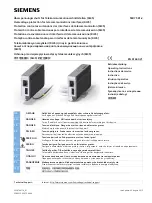
5SD7 581-2
Brand: Siemens Pages: 3

7SG14 Duobias-M-200
Brand: Siemens Pages: 20
11-C-9100-01
Brand: Siemens Pages: 29
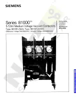
81000 90H35
Brand: Siemens Pages: 32

Arcteq AQ01
Brand: Siemens Pages: 48

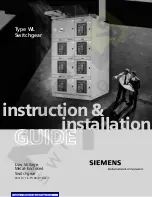
SDV7
Brand: Siemens Pages: 56

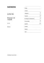
SIPROTEC 7XR8004
Brand: Siemens Pages: 70

SIPROTEC 7SJ46
Brand: Siemens Pages: 77
SIPROTEC 7SC805
Brand: Siemens Pages: 158

8PQ9801-8AA54
Brand: Siemens Pages: 160

SIPROTEC 7RW600
Brand: Siemens Pages: 168

SIPROTEC 4 7VE61
Brand: Siemens Pages: 330

SIPROTEC 7ST6
Brand: Siemens Pages: 356

SIPROTEC 4 7SD80
Brand: Siemens Pages: 416

SIPROTEC 5
Brand: Siemens Pages: 490

AP-S15A
Brand: Atlas IED Pages: 12


