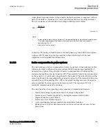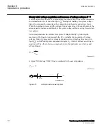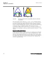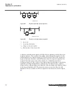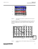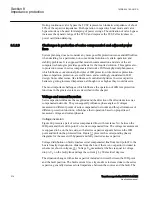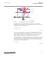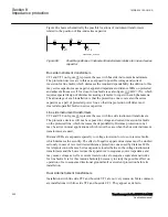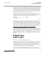
network with and without series capacitor. Possible effects of spark gap flashing or
MOV conducting are neglected. The time dependence of fault currents and the
difference between them are of interest.
en06000609.vsd
~
e
G
(t)
i
L
(t)
R
L
jX
L
-jX
C
F
IEC06000609 V1 EN-US
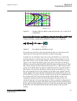
Figure 96:
Simplified equivalent scheme of SC network during fault conditions
We consider the instantaneous value of generator voltage following the sine wave
according to equation
(
)
sin
w
l
=
×
× +
G
G
e
E
t
EQUATION1904 V1 EN-US
(Equation 61)
The basic loop differential equation describing the circuit in figure
without series
capacitor is presented by equation
(
)
sin
w
l
×
+
× =
×
× +
L
L
L
L
G
di
L
R i
E
t
dt
EQUATION1905 V1 EN-US
(Equation 62)
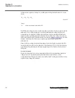
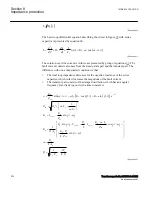
The solution over line current is presented by group of equations
(
)
(
)
(
)
(
)
0
2
2
sin
sin
w
l j
l j
w
w
j
- ×
=
é
ù
=
×
× + -
+
-
×
-
×
ê
ú
ë
û
=
+
×
æ
ö
×
=
ç
÷
è
ø
L
L
R
t
L
G
G
L
L t
L
L
L
L
E
E
i
t
I
e
Z
Z
Z
R
L
L
atg
R
EQUATION1906 V1 EN-US
(Equation 63)
The line fault current consists of two components:
•
The steady-state component which magnitude depends on generator voltage and
absolute value of impedance included in the circuit
•
The transient DC component, which magnitude depends on the fault incident angle
decays with the circuit time constant
1MRK 504 163-UUS A
Section 8
Impedance protection
Transformer protection RET670 2.2 ANSI
219
Application manual
Summary of Contents for RELION RET670
Page 1: ...RELION 670 SERIES Transformer protection RET670 Version 2 2 ANSI Application manual ...
Page 2: ......
Page 48: ...42 ...
Page 64: ...58 ...
Page 74: ...68 ...
Page 104: ...98 ...
Page 194: ...188 ...
Page 518: ...512 ...
Page 618: ...612 ...
Page 648: ...642 ...
Page 666: ...660 ...
Page 672: ...666 ...
Page 682: ...676 ...
Page 844: ...838 ...
Page 868: ...862 ...
Page 956: ...950 ...
Page 964: ...958 ...
Page 1004: ...998 ...
Page 1014: ...1008 ...
Page 1015: ...1009 ...

