10-2
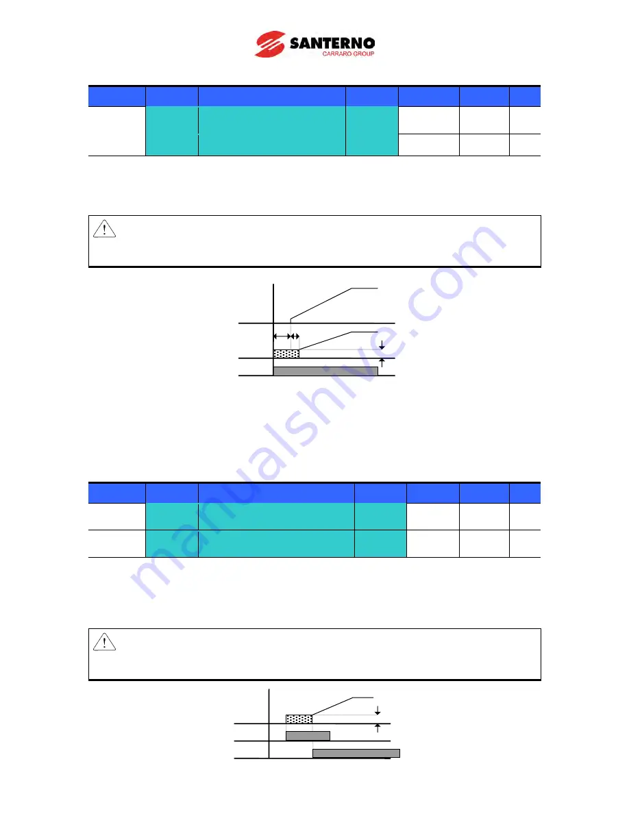
DC brake at start
Group
Display
Parameter Name
Setting
Range
Default Unit
Function
group 1
F12
[DC Brake start current]
-
0 ~ 200
50
%
F13
[DC Brake start time]
-
0 ~ 60
0
sec
F12: It sets the level as a percent of H33 – [Motor rated current].
F13: Motor accelerates after DC current, set in F12, is applied for this time.
Caution:
If excessive DC Brake voltage is set or DC Brake time is set too long, it may cause motor
overheating and damage the motor.
Setting F12 or F13 to 0 will disable Starting DC brake.
t: = when DC brake at start is applied, the output frequency increases after t time, or rather when the
inverter output voltage reaches the residual voltage due to DC brake
DC brake hold
Group
Display
Parameter Name
Setting
Range Default Unit
Function
group 1
F12
[DC Brake start current]
-
0 ~ 200 50
%
I/O group
I19
[Multi-function Input
terminal P3 Function select] 11
0 ~ 29
2
F12: It sets the level as a percent of H33 – [Motor rated current].
Select a terminal to issue a command of DC brake at a stop among P1 to P8.
If P3 terminal is set for this function, set I19 to 11 {DC brake hold}.
Caution:
If excessive DC Brake current is set or DC Brake hold time is set too long, it may cause motor
overheating and damage the motor.
Freq.
Current
Run
command
F13
t
F12
Current
Run command
F12
P3
Freq.
Summary of Contents for Sinus M
Page 10: ......
Page 15: ...1 5 Notes...
Page 16: ......
Page 50: ...6 4 Notes...
Page 78: ...8 4 Notes...
Page 114: ...10 14 Normal PID block diagram H54 0...
Page 115: ...10 15 Process PID block diagram H54 1...
Page 150: ...10 50 Notes...
Page 174: ......
Page 192: ...13 18 Notes...
Page 204: ......
Page 219: ...17 1 CHAPTER 17 EC Declaration of Conformity...


