


10-38
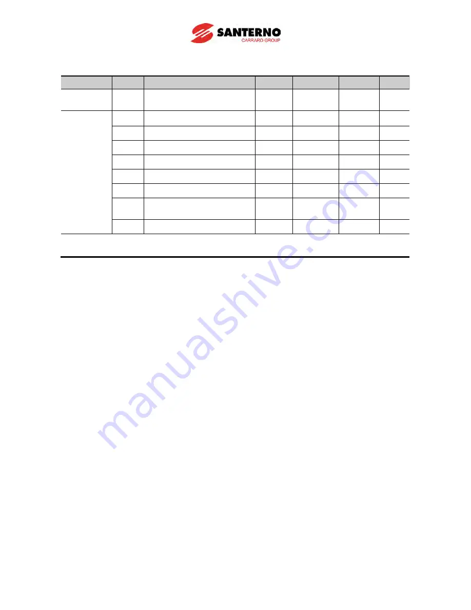
10.18 External brake control
Group
Code
Name
Set nr.
Limit
Default
Unit
Function
Group 2
H40
Controlling method select
0
0~3
0
In/Output
Group
I82
Brake open current
-
0~180.0
50.0
%
I83
Brake open delay time
-
0~10.00
1.00
Sec.
I84
Brake open CW Freq.
-
0~400
1.00
Hz
I85
Brake open CCW Freq.
-
0~400
1.00
Hz
I86
Brake close delay time
-
0~10.00
1.00
Sec.
I87
Brake close Freq.
-
0~400
2.00
Hz
I54
Multi-function output terminal
select
19
0~ 19
12
I55
Multi-function relay select
19
0~ 19
17
I82~87 is visible only when I54 or I55 is set to 19.
Used to control on, off operation of electronic brake of a load system. It only operates when
the set value of control mode (H40) is 0 (V/F control). Build sequence after checking set
control mode.
When the brake control is operating, DC brake and dwell run do not operate when starting
up.
Brake open Sequence
When the electric motor is given instructions to run, the inverter accelerates CW or CCW to
the brake open frequency (I84, I85). After reaching the brake open frequency, the current
running through the motor reaches brake open current (I82) and puts out brake open signals to
multi-function output terminals or output relays that are set for brake control.
Brake close sequence
During run, the electric motor decelerates when stop instruction is given. When output
frequency reaches brake close frequency, it stops decelerating and puts out brake close signal
to the set output terminal. Frequency turns “0” after keeping the frequency for brake close
delay time (I86).
Summary of Contents for Sinus M
Page 10: ......
Page 15: ...1 5 Notes...
Page 16: ......
Page 50: ...6 4 Notes...
Page 78: ...8 4 Notes...
Page 114: ...10 14 Normal PID block diagram H54 0...
Page 115: ...10 15 Process PID block diagram H54 1...
Page 150: ...10 50 Notes...
Page 174: ......
Page 192: ...13 18 Notes...
Page 204: ......
Page 219: ...17 1 CHAPTER 17 EC Declaration of Conformity...


