10-12
10.7 PID control
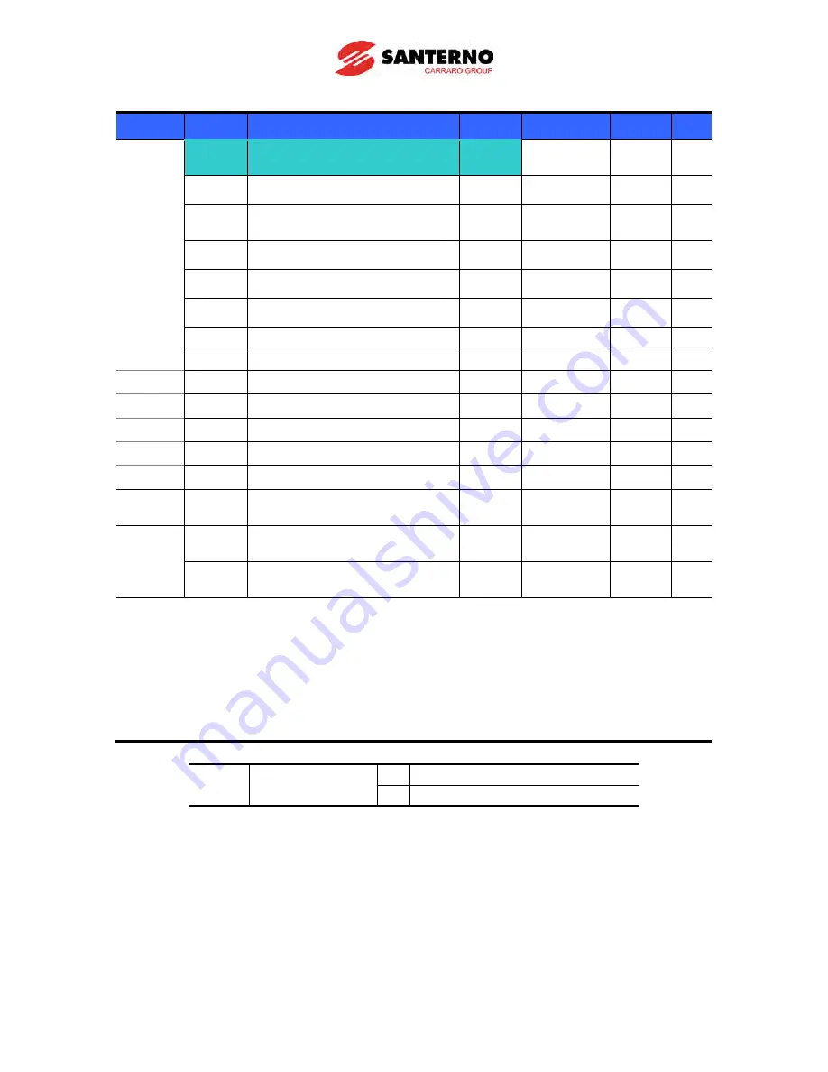
Group Display
Parameter Name
Setting
Range
Default Unit
Function
group 2
H49
[PID Operation select]
1
0 ~ 1
0
-
H50
[PID Feedback select]
-
0 ~ 1
0
-
H51
[Proportional gain for PID
control]
-
0 ~ 999.9
300.0
%
H52
[Integral time for PID control]
-
0.1~ 32.0
1.0
sec
H53
[Derivative time for PID control ] -
0.0~30.0
0
sec
H54
[PID control mode select]
-
0 ~ 1
0
-
H55
[PID output frequency high limit] -
0.1 ~ 400
60.0
Hz
H56
[PID output frequency low limit] -
0.1 ~ 400
0.50
Hz
H57
[PID reference source select]
-
0~4
0
Hz
H59
[Inverse PID]
-
0~1
0
-
H61
[Sleep delay time]
-
0.0~2000.0 60.0
-
H62
[Sleep frequency]
-
0.00~400
0.00
Hz
H63
[Wake-up level]
-
0.0~100.0
35.0
%
I/O
group
I17~
I24
[Multi-function input terminal
P1-P8 define]
21
0 ~ 29
-
-
Drive
group
rEF
[PID reference]
-
0~400
/0~100
0.00
/0.0
Hz
/%
Fbk
[PID feedback]
-
0~400
/0~100
0.00
/0.0
Hz
/%
In order to control the amount of following water, pressure and temperature, do PID
control to inverter output frequency.
Select H49 of function group 2 as a 1 (PID drive select). Then REF and FBK category
show. Set PID reference value in REF and real PID feedback amount is monitored at the
FBK
PID drive is classified as Normal PID mode and Process PID mode. It can be set in H54
(PID mode select)
H50: Select the feedback type of PID controller.
H50
[PID Feedback
select]
0
Terminal I input (0 ~ 20[mA] )
1
Terminal V1 input (0 ~ 10[V])
H51: proportional term (P), multiplying the difference between the reference (value to be
obtained from the physical quantity to adjust) and the feedback (value measured by the
physical quantity). That difference is called “error” and is multiplied by a constant (H51), “Prop.
Gain”). When H51 increases, the incidence of the proportional term in the regulator output
signal also increases (regulator becomes more “sensitive”) if the error is the same. Instability
occurs if H51 value is set too high.
H52: Integral time is important because allows to reduce to 0 the error at running operation
in order to keep the same value for both reference and feedback. Integral gain set the needed
time to correct the accumulated error. For example if H52 is set to 1 sec and the error
Summary of Contents for Sinus M
Page 10: ......
Page 15: ...1 5 Notes...
Page 16: ......
Page 50: ...6 4 Notes...
Page 78: ...8 4 Notes...
Page 114: ...10 14 Normal PID block diagram H54 0...
Page 115: ...10 15 Process PID block diagram H54 1...
Page 150: ...10 50 Notes...
Page 174: ......
Page 192: ...13 18 Notes...
Page 204: ......
Page 219: ...17 1 CHAPTER 17 EC Declaration of Conformity...


