


Instrument Function
R&S
®
SMBV100A
184
Operating Manual 1176.8016.02 ─ 17
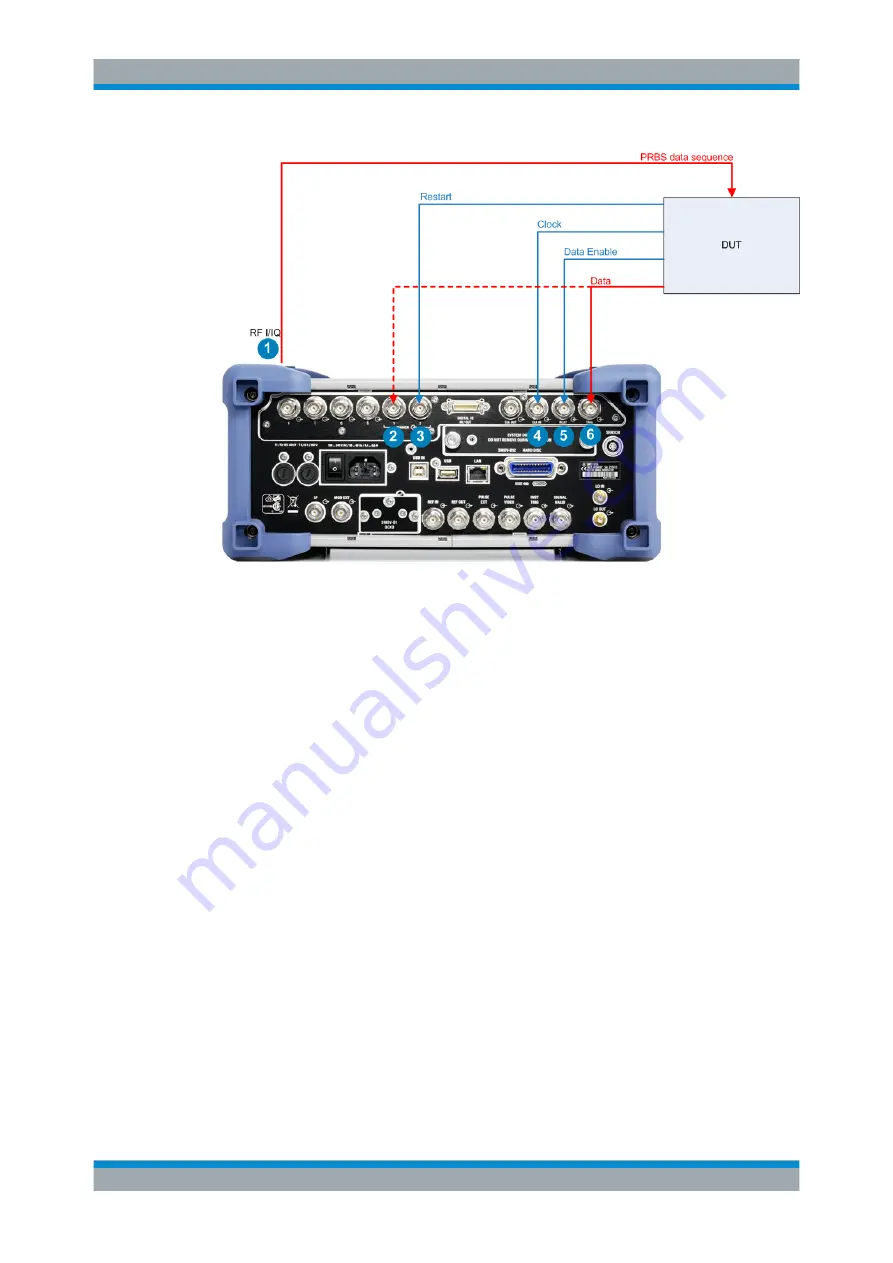
Figure 5-1: Test setup for bit or block error rate measurement
1 = PRBS data sequence (RF output connector (front)), see
2 = Data (MARKER 1 connector (rear)), alternatively to the TRIG connector, see
3 = Restart (MARKER 2 connector (rear)), BER measurement only, see
.
4 = Clock (CLOCK IN connector (rear)), see
.
5 = Data enable (NEXT connector (rear)),
6 = Data (TRIG connector (rear)), see
and the following sections.
5.4.2 PRBS Data
To detect faulty bits using the BER measurement, you must know the data generation
polynomial. The PRBS sequences are used as the method for computing the data (see
Chapter 5.9.2.1, "Internal PRBS Data and Data Patterns"
random bit sequences are repeated periodically, depending on the selected polyno-
mial. A randomly selected initial status yields exactly one subsequent status. The initial
status and therefore the subsequent status occur only once in the whole sequence.
Hence an advantage of the PRBS data is that the bit error detector must know only the
polynomial but not the entire sequence. At measurement start, the feedback shift regis-
ter is filled once with the applied data sequence (which corresponds to the synchroni-
zation time) and is subsequently switched from "fill" to "feedback". This function cre-
ates a defined initial status and generates the same data that the applied data stream
has. Faulty bits can thus be identified and counted by comparing the received data with
the results obtained from the shift register.
Creating a defined initial status makes it possible to start the analysis anywhere in the
bit stream, i.e. the bit-stream source and the analyzer need not be synchronized.
Bit and Block Error Rate Measurements


